Multi-band antenna

Active Publication Date: 2021-04-01
AIRBUS OPERATIONS SAS +1
View PDF0 Cites 3 Cited by
  • Summary
  • Abstract
  • Description
  • Claims
  • Application Information

AI Technical Summary

Benefits of technology

[0006]The present invention may be embodied to provide improved multi-band antennas which are thin and inexpensive, and who

Problems solved by technology

However, when the antenna is attached to the airplane fuselage, it forms

Method used


Image

  • Multi-band antenna
  • Multi-band antenna
  • Multi-band antenna

Examples


Example

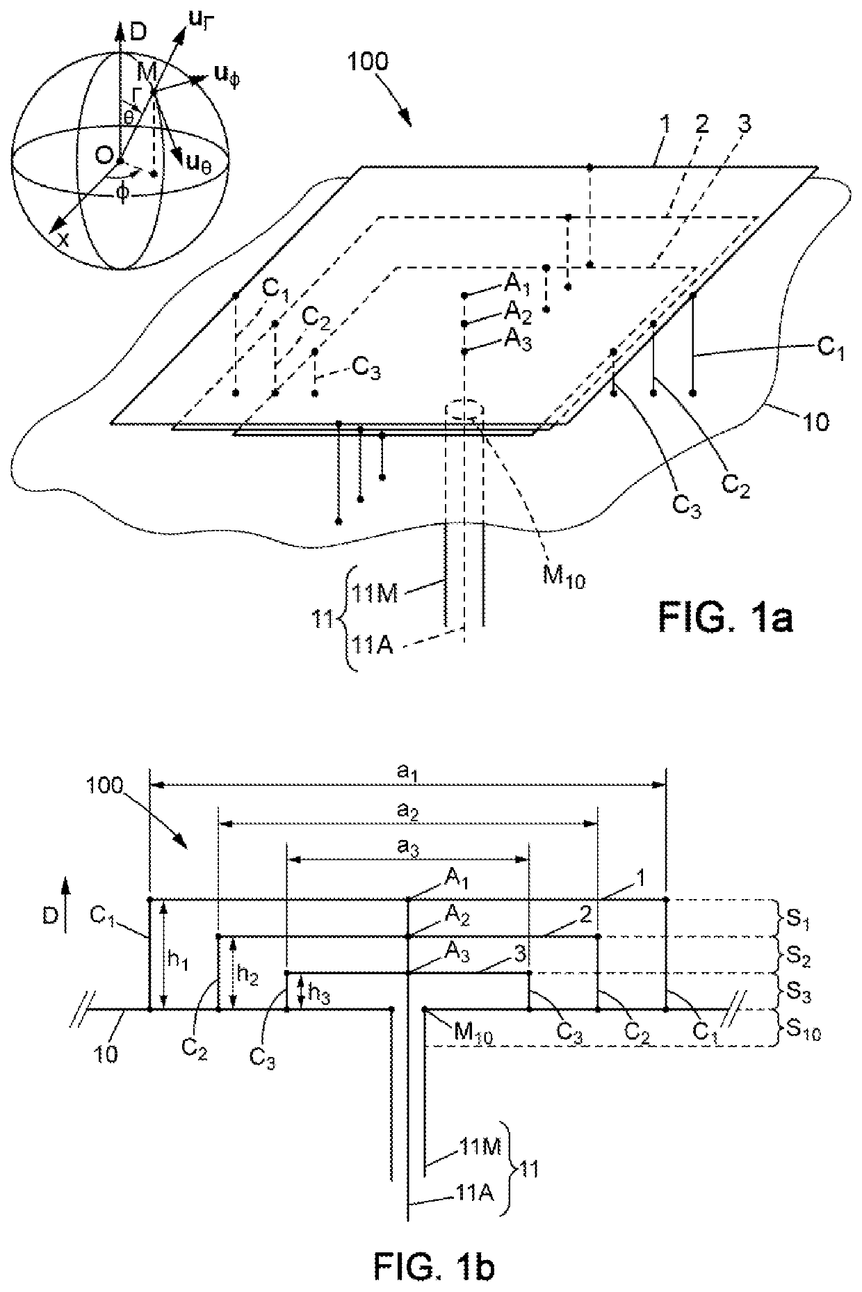
[0041]For clarity sake, the dimensions of the elements which are shown in [FIG. 1a], [FIG. 1b], and [FIG. 2] do not correspond to actual dimensions nor to actual dimension ratios. In addition, identical references indicated in different figures designate elements which are identical or have identical functions.

[0042]According to [FIG. 1a] and [FIG. 1b], a multi-band antenna 100 comprises a metal plate 10, called the metal base plate or base plate, and three metal patches 1, 2 and 3 which are parallel to the base plate 10 and distanced from it by different distances h1, h2 and h3, respectively. The distances h1-h3 are measured in a direction D of superposition of the patches 1-3, which may be perpendicular to the base plate 10. Also, the differences between the distances h1 and h2 on the one hand, and between h2 and h3 on the other hand, may be identical. The base plate 10 is larger, such as having a surface area five to ten times or more, than each of the patches 1-3. In addition, t...


PUM


Abstract

A multi-band antenna (100) including a metal base plate (10) forming an electrical ground plane, and a plurality of metal patches (1 to 3) superimposed on top of the metal base plate. The metal patches are connected in parallel between a signal lead wire (11A) and the metal base plate. The metal patches have respective surface areas which increase with the distance of each metal patch from the metal base plate. The antenna provides as many different resonant frequency values as there are patches.

Description

RELATED APPLICATION[0001]This application claims priority to French Patent Application 19 10719, filed Sep. 27, 2019, the entirety of which is incorporated by reference.TECHNICAL FIELD[0002]This description concerns a multi-band antenna as well as a method for manufacturing such an antenna. The antenna described is particularly suitable for installation on an aircraft.BACKGROUND[0003]Many applications require the use of multi-band antennas, particularly data communication between an airplane and the ground infrastructure of an airport. Such a communication link can in particular enable the transmission of data from the airplane when it is located near the airport or parked at its boarding gate, to an operator of the commercial line served by the airplane or to an aircraft maintenance operator. The Gatelink system, for example, provides a high speed wireless communication protocol for such an application. However, when the antenna is attached to the airplane fuselage, it forms a barr...

Claims


Application Information

Patent Timeline
IPC IPC(8): H01Q5/15H01Q5/357H01Q1/28
CPCH01Q5/15H01Q1/28H01Q5/357H01Q9/0414H01Q21/30H01Q1/38H01Q9/0421
Inventor MARTEL, CÉDRIC
Owner AIRBUS OPERATIONS SAS
Why Eureka
Try Eureka