Illumination device and display device

a technology which is applied in the field of illumination device and display device, can solve the problems of low utilization efficiency of light from the light source of the backlight, limited thickness, cost, etc., and achieves the effects of high efficiency, low cost and low cos

Active Publication Date: 2012-08-28
DAWNCREST IP LLC
View PDF9 Cites 0 Cited by
  • Summary
  • Abstract
  • Description
  • Claims
  • Application Information

AI Technical Summary

Benefits of technology

[0010]The present invention provides a display device including an illumination device and a display element, the illumination device including a light source and a light guide plate, the light guide plate having an incident surface on which light from the light source enters, an exit surface from which illumination light is output, and an opposing surface opposite to the exit surface, the display element being placed above the exit surface of the illumination device. In addition, the opposing surface of the light guide plate includes at least two pyramidal microprisms formed thereon in an area overlapping an opening of a liquid crystal panel. Further, the incident surface includes an entrance portion provided thereon, which is a semicircular depressed portion. An arrangement angle of the microprisms is optimized so that light from the entrance portion may be output with high efficiency.
[0011]With this structure, an illumination device that utilizes light from a light source in a highly efficient manner and that is inexpensive and thin may be realized. When the illumination device is combined with the liquid crystal panel, a display device that does not generate moiré may be realized. Further, the illumination device may be adapted to a plurality of light sources.

Problems solved by technology

The conventional backlight structure uses the prism sheet and hence has limits in thickness, luminance efficiency, and cost.
Moreover, utilization efficiency of the light from the light source of the backlight is very low.
In addition, the conventional microprism array backlight is only adapted to a single point light source, and it has been impossible to increase the number of the light sources to two or more.
Further, the structure without the prism sheet has a problem in that moiré (interference) is likely to occur when a liquid crystal panel is placed thereon.

Method used


Image

  • Illumination device and display device
  • Illumination device and display device
  • Illumination device and display device

Examples


example 1

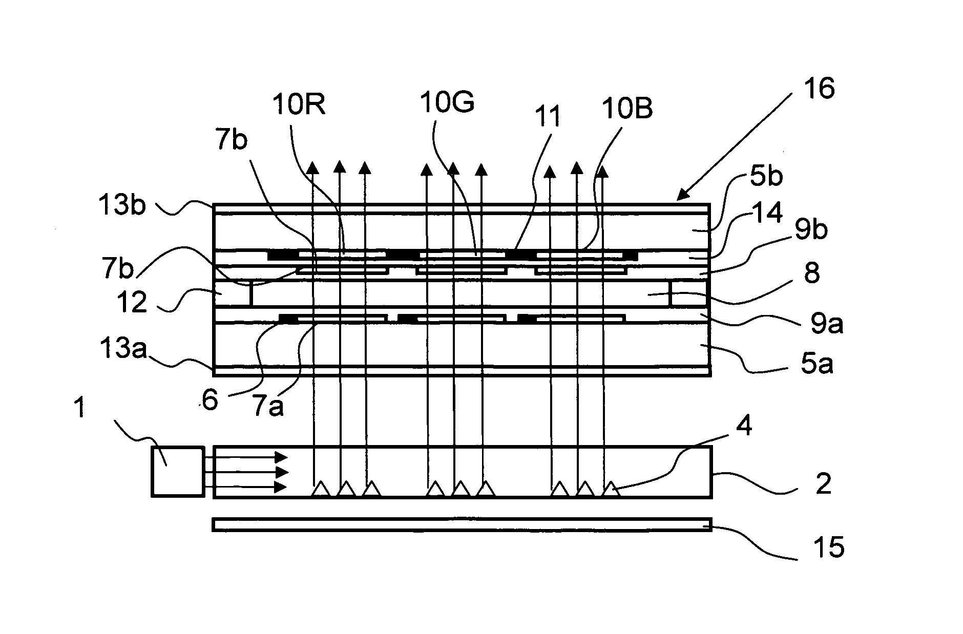
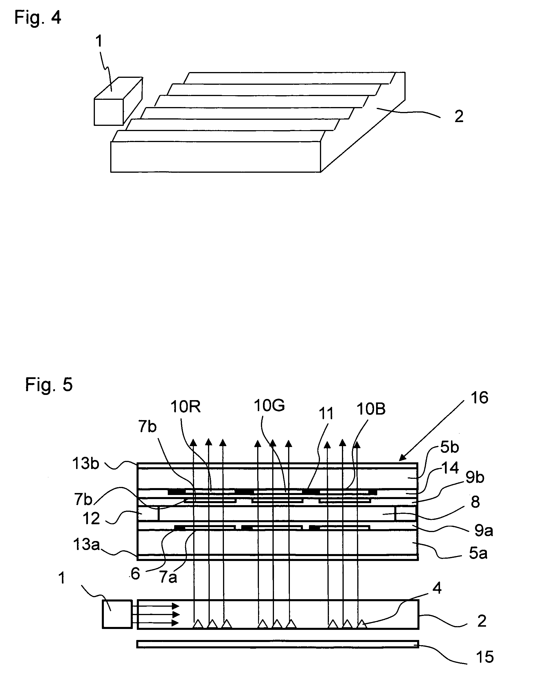
[0026]A display device of Example 1 is described with reference to FIGS. 1 to 5.

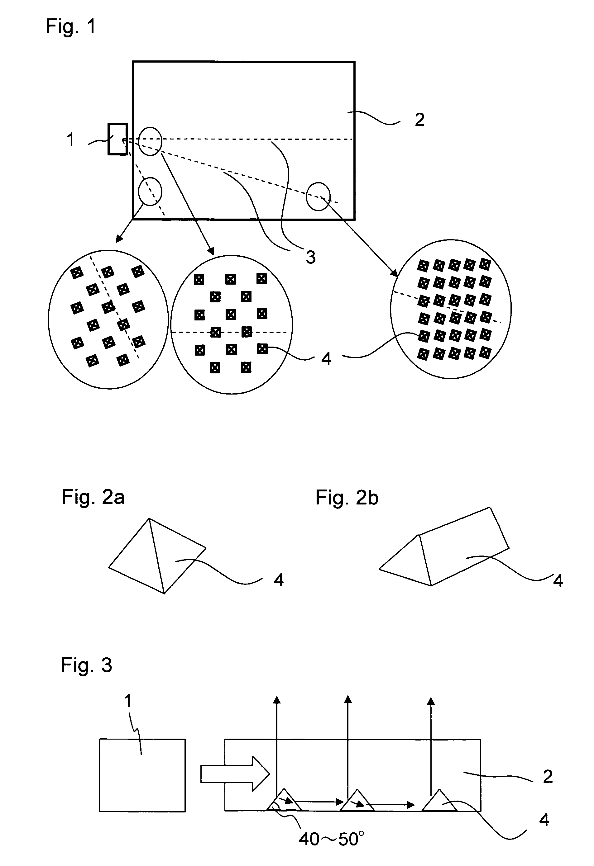
[0027]FIG. 1 schematically illustrates a front structure of an illumination device of Example 1. In Example 1, a white light emitting diode (LED) package is used as a light source 1 of a backlight. The white LED package is of a type in which a blue LED is potted in a yellow fluorescent material. A light guide plate 2 is placed in front of the light source 1 and guides light emitted from the light source 1. In Example 1, the light source 1 is a point light source, and a white LED of a side view type is given as an example. However, the light source 1 may also be a white LED of a top view type or round lamp type, or an LED of a color other than white. The light guide plate 2 is a molded component formed of a transparent resin such as ZEONOR, polymethylmethacrylate (PMMA), or polycarbonate (PC). Light from the light source 1 propagates inside the transparent light guide plate 2, and is radiated to a display...

example 2

[0036]FIGS. 6a and 6b are front views each schematically illustrating a light guide plate 2 of Example 2. The light guide plates 2 of Example 2 are different from the light guide plate 2 of Example 1 in the shape of the entrance portion of the light guide plate 2. A semicircular depressed portion is provided to the incident surface of the light guide plate 2 to correspond to the light source 1, and functions as the entrance portion. When the entrance portion is a semicircular depressed portion as in Example 2, the light from the light source 1 is refracted by the semicircular entrance portion and then enters the light guide plate 2. Therefore, the light path is different from that of Example 1. Accordingly, optimum arrangement of the microprisms 4 is different from that of Example 1.

[0037]The entrance portion of FIG. 6a has a shape of a semicircle with a sharp tip, and the entrance portion of FIG. 6b has a shape of a semicircle with a blunt tip. A light path 3a and a light path 3b a...

example 3

[0038]FIG. 7 is a front view schematically illustrating a light guide plate 2 of Example 3. The light guide plate 2 of Example 3 is different from the light guide plates 2 of Examples 1 and 2 in the number of light sources 1 and an arrangement method of the microprisms 4. In Example 3, alight source 1c and a light source 1d are provided with respect to the incident surface of the light guide plate 2. Microprisms 4c and microprisms 4d are arranged on the light guide plate 2. The microprisms 4c and the microprisms 4d respectively correspond to the light source 1c and the light source 1d. The microprisms 4c and the microprisms 4d are alternately arranged. Each of the microprisms 4c is arranged so that a base of a mirror surface thereof is at about 90 degrees with respect to a light path 3c connecting the light source 1c and each of the microprisms 4c. Similarly, each of the microprisms 4d is arranged so that a base of a mirror surface thereof is at about 90 degrees with respect to a li...


PUM


Abstract

A display device has at least one light source for emitting light and a light guide plate having a first surface for inputting light emitted from the at least one light source, a second surface for outputting illumination light, and a third surface opposite to the second surface. A display element having dots for displaying image information is arranged over the second surface of the light guide plate for receiving the illumination light. At least two microprisms are arranged on the third surface of the light guide plate in areas overlapping the dots of the display element. Each microprism has a height in the range of from 1 μm to 10 μm and a mirror surface for reflecting light emitted from the at least one light source. Each mirror surface has a base disposed perpendicular to a light path of the light emitted from the at least one light source.

Description

BACKGROUND OF THE INVENTION[0001]1. Field of the Invention[0002]The present invention relates to a display device used in a portable information device such as a cellular phone or a mobile computer.[0003]2. Description of the Related Art[0004]Conventionally, a liquid crystal display device that is small and thin and consumes less power is often used as a color image display device used in a portable information device such as a cellular phone or a mobile computer.[0005]The liquid crystal display device includes a backlight as an illumination device. One known type of backlight is an edge-lit illumination device in which light from a light source enters on a side surface of a light guide plate and output from a top surface (hereinafter, referred to as exit surface) of the light guide plate. The light source includes a point light source such as a cathode ray tube or a light emitting diode (LED). The light guide plate has a surface (hereinafter, referred to as opposing surface) opposi...

Claims


Application Information

Patent Timeline
Patent Type & Authority Patents(United States)
IPC IPC(8): F21V7/04
CPCG02B6/0036G02B6/0021
Inventor KURIHARA, MAKOTODEJIMA, NORIHIRO
Owner DAWNCREST IP LLC
Why Eureka
Try Eureka