High power laser diode array comprising at least one high power diode laser and laser light source comprising the same

a laser diode array and laser light source technology, applied in semiconductor lasers, optical elements, instruments, etc., can solve the problems of high asymmetry of beam quality of such a high-power laser diode, poor symmetry of collimated output laser beams for many applications, and difficult to achieve the effect of achieving high asymmetry, simple and cost-efficient configuration, and less tight tolerances

Inactive Publication Date: 2010-07-06
FRAUNHOFER USA CENT FOR LASER TECH
View PDF6 Cites 35 Cited by
  • Summary
  • Abstract
  • Description
  • Claims
  • Application Information

AI Technical Summary

Benefits of technology

[0015]It is an object of the present invention to provide a simple arrangement of diode lasers wherein each output laser beam is individually collimated in fast and slow axis by a set of dedicated lenses or lens sections and wherein an output laser beam profile is formed, without the use of an optical interleaver, consisting of a plurality of fast and slow axis collimated or focussed output laser beams arranged adjacent to each other, i.e. next to each other, in a seamless manner in one dimension or in two dimensions with an optical fill factor of 100% or close to 100%. It is further a related object of the present invention to arrange the diode lasers such that all diode lasers are effectively coupled into optical fibers by imaging all facets of the diode lasers on the fiber end by means of reflective or refractive optics only, avoiding any beam shaping optics for rearranging the emission of diode lasers. It is a further related object of the present invention to further enhance the imaging and optical loss characteristics of the high power laser diode of the above configuration and at the same time to enable a simple and cost-efficient configuration for fast and slow axis collimation of the output laser beams at less tight tolerances. According to a further related aspect of the present invention corresponding methods for manufacturing such a high power laser diode are to be provided.
[0019]According to an embodiment the laser light emitters are displaced relative to each other in a chessboard-like manner so that in combination with a suitable optical means, such as an array of parabolic hollow mirrors or refractive optical lenses, the output laser beams are arranged next to each other in a seamless manner in one or two dimensions, i.e. such that neighbouring output laser beams are substantially adjacent to each other, without a significant gap of low or vanishing light intensity therebetween. In this manner an optical fill factor of the output laser beam profile of 100% or close to 100% is achieved. More specifically the output laser beam profile preferably consists of a plurality of output laser beams that are collimated or focussed in fast axis direction and collimated or focussed in slow axis direction and arranged in a chessboard-like manner. Output laser beams of neighbouring rows may be displaced by half a beam pitch which enables to efficiently generate output laser beam profiles of arbitrary shape, such as circular, elliptical, line-shaped, rectangular, etc. beam profiles.
[0021]According to an embodiment the fast axis collimating means is or are integrated into a respective high power laser diode, using a planar substrate means which receives or supports the fast axis collimating optical element, such as a refractive lens, a diffractive optical element or a reflective mirror. Thus, a stable and precise fast axis collimation is accomplished.
[0023]According to another preferred embodiment several or all of said parabolic hollow mirrors are formed in a common substrate by micro-machining or diamond-machining of said substrate, preferably a copper body, or by press-forming of a glass, which enables an efficient mounting and cooling of the slow axis collimating means.
[0024]According to another embodiment, the common substrate is actively cooled, preferably by a fluid flowing through the common substrate, to avoid excessive heating of the common substrate due to reflective and / or absorptive losses caused by said parabolic hollow mirrors.
[0026]According to another embodiment, the laser light emitters are aligned along at least two rows, at equidistant spacings between two neighbouring laser light emitters of a respective row, wherein neighbouring rows of high power laser diodes are alternately shifted in fast axis direction by a fraction 1 / n of said spacing (n being an integer larger than or equal to 1, preferably equal to 2). This optical arrangement enables an efficient interleaving of output laser beams in order to obtain an output laser beam profile consisting of a plurality of output laser beams interleaved in a chessboard-like, seamless manner.

Problems solved by technology

However, it is noted that the beam quality of such a high power laser diode is highly asymmetric.
The issue of asymmetric beam quality in fast and slow axis is much more severe for high power arrays, with multiple single chips arranged in one semiconductor next to each other in slow axis direction.
Nevertheless, the symmetry of said collimated output laser beams is not satisfactory for many applications.
This approach usually requires precise alignment of multiple micro-optical lenses in six axes, which makes the whole setup relatively complex and expensive.
Nevertheless, a substantial loss of beam quality is experienced because of unavoidable tolerances in the parts, such as smile of the lens or diode array or the optical components for beam shaping, as well as in the alignment of the laser light emitter(s) to the associated optical component(s) and the optical components themselves.
The set-up relies on highly accurate placement of the diode laser on the heat sink in six axis, which is practically very challenging.

Method used


Image

  • High power laser diode array comprising at least one high power diode laser and laser light source comprising the same
  • High power laser diode array comprising at least one high power diode laser and laser light source comprising the same
  • High power laser diode array comprising at least one high power diode laser and laser light source comprising the same

Examples


Embodiment Construction

[0052]With reference to FIG. 4a to 5c the configuration of a high power diode laser for use in a high power laser diode array according to the present invention and the most important steps for manufacturing such a high power diode laser will be described in more detail.

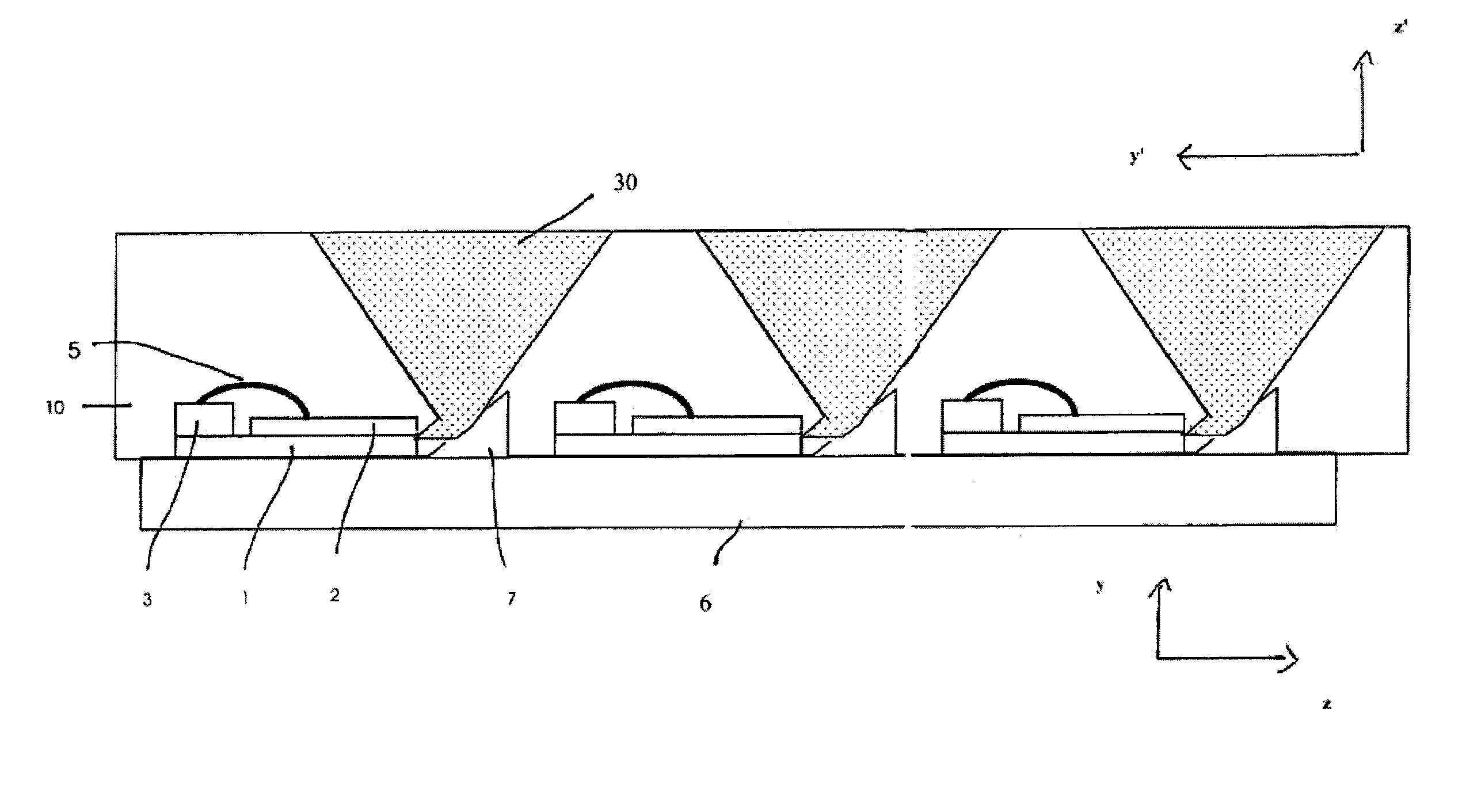
[0053]As shown in FIGS. 4a and 4b, the diode laser chip 2 is mounted on the top surface of a submount 1, which is of a substantially rectangular shape having straight edges perpendicular to each other. The submount 1 can be made of any material suitable for supporting a laser diode chip. Preferably the submount is of a high heat conductivity material in order to spread heat generated by the diode laser chip 2 to a carrier 6 supporting the submount 1. Furthermore, the material of the submount 1 preferably has the same coefficient of thermal expansion as the semiconductor material of the diode laser chip. Suitable materials for the submount 1 that shall not be deemed limiting the present invention are: AlN, CuWo or dia...


PUM


Abstract

Array comprising high power laser diode comprising laser light emitters, each defining, in a direction perpendicular to direction of propagation of an output laser beam, a fast axis and a slow axis; fast axis collimating means for collimating output laser beams in fast axis direction; and slow axis beam shaping means for collimating or focussing output laser beams in slow axis direction, said slow axis beam shaping means disposed external to said high power laser diode; wherein said laser light emitters are displaced relative to each other in fast axis direction or in fast and slow axis direction by equidistant spacings, respectively; and including optical means for forming output laser beam profile in far field of all laser light emitters consisting of said fast and slow axis collimated or focussed output laser beams arranged adjacently in seamless manner in one or two dimensions with optical fill factor of about 100%.

Description

CROSS-REFERENCE TO RELATED APPLICATIONS[0001]The present application is related to and claims priority and benefit under 35 U.S.C. §119(e) to U.S. Provisional Application No. 60 / 988,577, filed 16 Nov. 2007, and is related to and claims priority under 35 U.S.C. §119(a) to European Application Nos. 08100714.8As, filed 21 Jan. 2008 and 08103278.1, filed 31 Mar. 2008, the entirety of each of which is fully incorporated herein by reference as if fully contained herein.FIELD OF THE INVENTION[0002]The present invention relates in general to high power diode lasers and relates in particular to a high power laser diode array comprising at least one high power diode laser having multiple emitters and more preferably comprising a plurality of high power diode lasers having multiple emitters, a method for manufacturing the same and an optical setup for coupling the output of such a high power laser diode array into an optical fibre.BACKGROUND OF THE INVENTION[0003]Most high power diode lasers a...

Claims


Application Information

Patent Timeline
Patent Type & Authority Patents(United States)
IPC IPC(8): H01S5/00H01S3/08
CPCH01S5/4012H01S5/405G02B19/0023G02B19/0028G02B19/0057H01S5/005H01S5/42
Inventor REGAARD, BORISSCHMIDT, THORSTENHEINEMANN, STEFAN
Owner FRAUNHOFER USA CENT FOR LASER TECH
Why Eureka
Try Eureka