[0015]It is an object of the present invention to provide a simple arrangement of diode lasers wherein each output laser beam is individually collimated in fast and slow axis by a set of dedicated lenses or lens sections and wherein an output laser beam profile is formed, without the use of an
optical interleaver, consisting of a plurality of fast and slow axis collimated or focussed output laser beams arranged adjacent to each other, i.e. next to each other, in a seamless manner in one dimension or in two dimensions with an optical
fill factor of 100% or close to 100%. It is further a related object of the present invention to arrange the diode lasers such that all diode lasers are effectively coupled into optical fibers by imaging all facets of the diode lasers on the
fiber end by means of reflective or refractive
optics only, avoiding any beam shaping
optics for rearranging the emission of diode lasers. It is a further related object of the present invention to further enhance the imaging and optical loss characteristics of the high power laser diode of the above configuration and at the same time to enable a simple and cost-efficient configuration for fast and slow axis collimation of the output laser beams at less tight tolerances. According to a further related aspect of the present invention corresponding methods for manufacturing such a high power laser diode are to be provided.
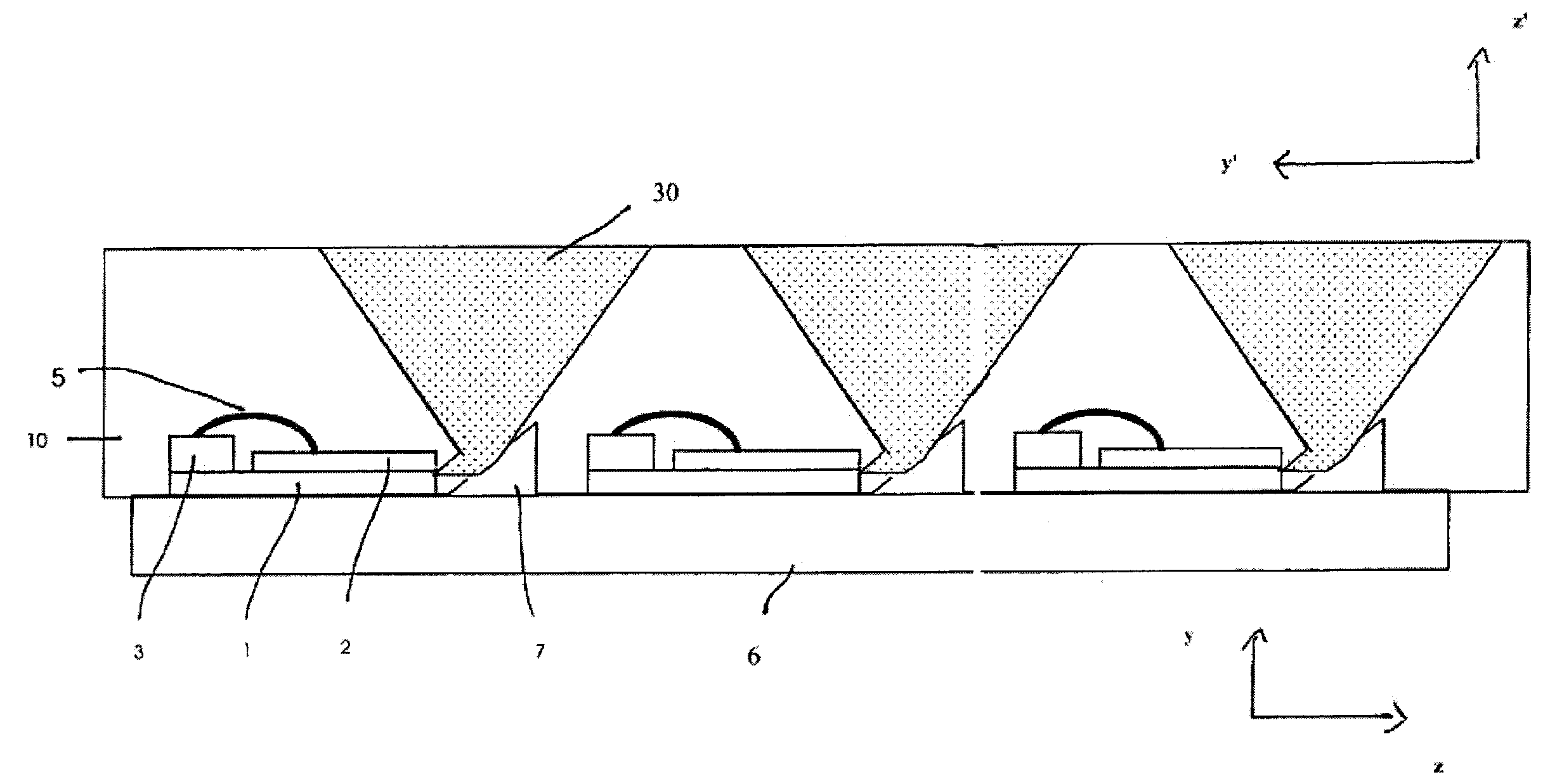
[0019]According to an embodiment the laser light emitters are displaced relative to each other in a chessboard-like manner so that in combination with a suitable optical means, such as an array of parabolic hollow mirrors or refractive optical lenses, the output laser beams are arranged next to each other in a seamless manner in one or two dimensions, i.e. such that neighbouring output laser beams are substantially adjacent to each other, without a significant gap of low or vanishing
light intensity therebetween. In this manner an optical
fill factor of the output laser beam profile of 100% or close to 100% is achieved. More specifically the output laser beam profile preferably consists of a plurality of output laser beams that are collimated or focussed in fast axis direction and collimated or focussed in slow axis direction and arranged in a chessboard-like manner. Output laser beams of neighbouring rows may be displaced by half a beam
pitch which enables to efficiently generate output laser beam profiles of arbitrary shape, such as circular, elliptical, line-shaped, rectangular, etc. beam profiles.
[0021]According to an embodiment the fast axis collimating means is or are integrated into a respective high power laser diode, using a
planar substrate means which receives or supports the fast axis collimating optical element, such as a
refractive lens, a diffractive optical element or a reflective mirror. Thus, a stable and precise fast axis collimation is accomplished.
[0023]According to another preferred embodiment several or all of said parabolic hollow mirrors are formed in a common substrate by micro-
machining or
diamond-
machining of said substrate, preferably a
copper body, or by press-forming of a glass, which enables an efficient mounting and cooling of the slow axis collimating means.
[0024]According to another embodiment, the common substrate is actively cooled, preferably by a fluid flowing through the common substrate, to avoid excessive heating of the common substrate due to reflective and / or absorptive losses caused by said parabolic hollow mirrors.
[0026]According to another embodiment, the laser light emitters are aligned along at least two rows, at
equidistant spacings between two neighbouring laser light emitters of a respective row, wherein neighbouring rows of high power laser diodes are alternately shifted in fast axis direction by a fraction 1 / n of said spacing (n being an integer larger than or equal to 1, preferably equal to 2). This optical arrangement enables an efficient
interleaving of output laser beams in order to obtain an output laser beam profile consisting of a plurality of output laser beams interleaved in a chessboard-like, seamless manner.

