Hybrid power control system

a power control system and hybrid technology, applied in the direction of electric variable regulation, process and machine control, instruments, etc., to achieve the effect of maximising the overall efficiency of the hybrid power control system, maximising the light emitted, and high degree of protection against damag

Active Publication Date: 2014-02-25
RADIANT RES
View PDF24 Cites 33 Cited by
  • Summary
  • Abstract
  • Description
  • Claims
  • Application Information

AI Technical Summary

Benefits of technology

[0096]A further advantage of the present invention is that it offers a high degree of protection against damage due to mis-wiring of the output connectors on the hybrid power control system. Traditional switching regulators or control systems for solid state lighting do not offer protection against wiring the anode connection of the switching device to ground or another switching device however the output drive stage topology taught within the scope of the present invention enables the output connectors for each drive stage to be mis-wired without causing catastrophic failure to the output drive stage components.
[0097]Another advantage of the present invention is that when multiple output drive stages are contained within the hybrid control system it is possible to dynamically change the power in each channel according to a maximum power level set by the hybrid control system. This enables for example the maximum output of the combined driver stages to be set to the maximum output power of an AC / DC switching regulator that powers the output stages. This dynamic power control enables the application to operate at any pre-defined power up to the maximum of the AC / DC power supply and thus maximising the overall efficiency of the hybrid power control system at the same time as maximising the light emitted from the illumination control system.
[0098]A further advantage is that, by controlling the voltage and type of voltage supplied by the power source in response to the type of light emitting device(s) used within the illumination system it is possible to optimise the overall lumens per watt efficiency of the illumination system. For example, today the majority of LEDs manufactured utilise DC voltage to energise which may require an AC voltage to DC voltage switch mode regulator however it is possible to directly connect AC driven LEDs which do not necessitate the need for an AC to DC switch mode regulator. Furthermore the power source may be obtained from a DC generator such as a Photovoltaic (solar) cell and therefore only a DC / DC switching regulator may be required increasing the overall efficiency of the hybrid power control system.
[0099]Other preferred features of the invention are defined in the dependent claims and may be further discussed hereinafter.
[0100]In one embodiment of the invention, a lighting controller for (O)LED products includes the combination of linear and switching regulator power supplies within a dynamic power control system configured in a buck (or other suitable) circuit topology to obtain significantly improved dimming performance at low load currents whilst increasing the dynamic current range to operate from micro-amps to multiple Amps across one or more output drive stage channels. The said embodiment includes the ability to dynamically share power across multiple drive stage channel outputs in a robust and reliable method retaining the ability to bond channels to increase effective current output of the controller or to implement common anode features to reduce the need of extra wiring between the controller and the lighting emitting device load.
[0101]A preferred embodiment of the present invention includes a means for controlling the power factor and the quality of power to the illumination system. Power factor is defined herein as the ratio of real power to apparent power. Power factor is a simple way to determine how much of the current contributes to real power in the device load. A power factor of one (unity or 1.00) indicates that 100% of the current is contributing to power in the device load while a power factor of zero indicates that none of the current contributes to power in the device load. Preferably, the power factor of the switch mode power supply unit used within one embodiment of the illumination system is ≧0.80, more preferably ≧0.98, so that, once the power is delivered to the device load, the amount of current returned is minimised. This is desirable because:

Problems solved by technology

Although PWM schemes are common place due to the simplicity of digital switching between two binary states of ON and OFF they have significant disadvantages including:1. Uneven power supply loading: By switching the light emitting device loads on and off at the same time causes the power supply to provide zero output or full output on a continuously switched basis which reduces the overall efficiency of the power supply unit (PSU)2. The Electromagnetic interference (EMI) of a PWM system is far more complicated than with other control methods as the changes in duty cycle results in a wide frequency range of noise being emitted.3. The amplitude of the EMI is increased as the forward current is increased as the pulsing currents through the electrical leads connecting the driver electronics to the illumination system fixtures may act as transmitters of radio frequency energy that could cause interference with other equipment as the interference is very high at the transition of the current switching.4. The pulsing of PWM systems for a variety of applications are not acceptable especially where high refresh rates are required.
For example, in TV and Film environments the camera's are usually digital and a mismatch between the camera capture frequency and the PWM fixed frequency results in poor quality imaging in both intensity and colour.5. The dimming dynamic range of PWM systems are usually very poor as the only way to dim the lighting loads is by reducing the duty cycle and at low duty cycles there is a very small percentage of time when the light emitting device is actually illuminated.
Some PWM systems offer high resolution 16-bit dimming (1:65535) ratios however as the dimming range is extended the maximum fixed frequency has to reduce which can results in visual flicker or a beating effect.6. PWM systems have a fixed maximum forward current and additional circuitry is required in order to change this adding extra cost and complexity to the design.7. PWM based systems are much less efficient at driving (O)LEDs when being dimmed in some circumstances up to 150% less efficient compared to DC or constant current reduction dimming as discussed by Gu, Y et al, in the SPIE 2006 paper entitled “Spectral and Luminous Efficacy Change of High-power LEDs under Different Dimming Methods”.
SPIE 6337, 63370J.8. Additional thermal and electrical stresses are placed on the lighting load as power is rapidly cycled ON and OFF causing thermal cycling that adds stress to the LED die or bond wires attached to the LED die.9. PWM systems make it more difficult to control complete illumination systems as it only has one variable (Duty Cycle) in which to change the control system output driver stage(s).
A third method often known as Direct Current (DC) dimming or Constant Current Reduction (CCR) has been used to power light emitting devices however the difficulty with such a technique is to obtain high efficiency from the driver output stages as they are usually implemented with linear power supplies or the dynamic dimming range is not high (1:100 or 1:200).
In addition, linear power supplies suffer from efficiency drops as the driver system input voltage deviates from that of the voltage required to power the emitting device(s).
Therefore, the bigger the voltage difference the more power is wasted as heat across the linear power supply components which, in turn, can cause early failure of components and reduces overall driver lifetime and efficiency.
A significant issue of the latest generation of (O)LED devices is that their efficiency to produce light from electrical current is so high that even at very low levels of current ie; 1-10 mA the light being emitted is considerably brighter than desired in many applications due to the sensitivity of the human eye.
These topologies are inflexible such that if different (O)LED light emitting device(s) are used with varying characteristics the performance of the power control system will at best be altered significantly but at worst not function correctly at all.
Furthermore where the illumination system fixture requires independently controlled light source channels such as in Red, Green, Blue and Amber the actual power used across all of the channels is significantly less than the maximum power for the combined channels and this results in the driver system operating at less than optimal performance.
Therefore, switching topologies are not suitable for precise or repeatable current control at low forward currents and the lowest current limit of a system is determined by the switching speed (or minimum pulse width) achieved by the MOSFET switching device.
Although this technique achieves a wider dynamic dimming range compared to a standard switching technique there are still pulses in the current through the light emitting device(s) load and maintains the majority of disadvantages attributed to the PWM dimming technique at lower currents.
Also the circuit topology described is configured such that it is not possible to operate said power system in a common anode topology for more than one light emitting device output.
In addition, the circuit topology described is not able to bond one or more output channels together to increase total (O)LED output current.
A further disadvantage of US patent 2009 / 0302779A1 is that the design does not contain fault tolerant error protection so if the anode terminal is shorted to ground or to the cathode of another output connector the switching IC or MOSFET would fail rendering the power controller inoperable.
If the switching frequency is too high there are switching losses which reduce the overall efficiency of the stage and EMC / EMI design becomes more complex.
Increasing the 
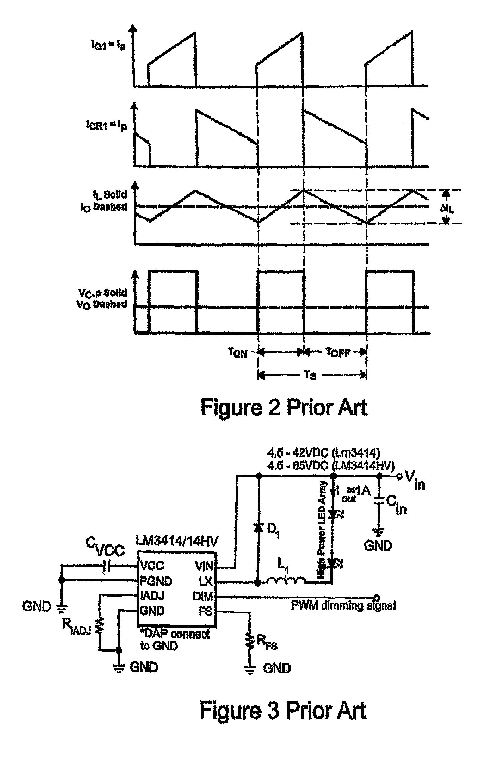
capacitance on the output stage means bulkier components and if the output voltage is high eg>20V then component costs increase.
Therefore, such switching designs are usually limited to being fixed once into production.
In addition, the LM3414 still suffers from the ability to channel bond multiple outputs, dim the output current in an analogue (or non PWM) fashion to low currents (The LM3414 datasheet indicates a minimum analogue dimming current of approximately 100 mA can be achieved) and cannot tolerate miss-wiring of the (O)LED outputs potentially resulting in catastrophic failure of the driver stage in application.
Consequently, linear regulators offer simple design and less EMI issues compared to switching power topologies however their efficiency, size and heat generation limit their scope to lower power applications.
They are, however, more complicated, their switching currents can cause electrical noise problems if not carefully suppressed, and simple designs may have a poor power factor.

Method used


Image

  • Hybrid power control system
  • Hybrid power control system
  • Hybrid power control system

Examples


Embodiment Construction

[0260]Referring to the drawings, FIG. 1a shows a prior art continuous conduction mode switching regulator circuit incorporating a switching device (Q1) a flyback diode (CR1) an energy storage device such as an inductor (L) an output filter using a capacitor (c) and a resistor (RC) and a load (R). FIG. 1b represents a schematic in the switched ON state of the circuit in FIG. 1a whilst FIG. 1c represents a schematic in the switched OFF state.

[0261]FIG. 2 illustrates the various current and voltage waveforms of the circuit highlighted in FIG. 1a as the continuous conduction mode circuit is being switched ON and OFF repeatedly.

[0262]FIG. 3 illustrates a prior art switching regulator circuit with analogue and PWM dimming inputs to dim the current through the LEDs.

[0263]FIG. 4 illustrates a schematic diagram outlining the main parts of an illumination system from input to output according to one embodiment of the present invention. As mentioned, the object of an AC to DC illumination syst...


PUM


Abstract

A hybrid power control system for providing dynamic power control to illumination systems in which a power source can supply any one of a range of AC or DC voltages. One or more switch mode power supplies incorporating one or more linear and switch mode regulator circuits combined to dynamically control current, voltage and power to the illumination system. A microprocessor or other integrated circuit device to receive and send control information in order to regulate the power to a light emitting device One or more output drive stage(s) capable of delivering a wide dynamic current range, channel bonding and protection circuitry compatible with standard or common anode illumination systems.

Description

CROSS-REFERENCE TO RELATED APPLICATIONS[0001]This application claims the benefit of Great Britain Patent Application Serial No. 1100691.3 filed on Jan. 17, 2011.TECHNICAL FIELD OF THE INVENTION[0002]The present invention relates to improvements in methods and apparatus to power light sources, and in particular but not exclusively, relates to a highly efficient and robust method and apparatus to dim or otherwise adjust brightness or regulate the power to light sources such as Light Emitting Diodes (LEDs), Organic Light Emitting Diodes (OLEDs) and other solid-state light source loads. More especially, an efficient, power configurable, high reliability hybrid control system using dynamic power regulation to increase the dimming dynamic range and power control of solid-state illumination systems.BACKGROUND OF THE INVENTION[0003]The use of LEDs in illumination systems are well known as they offer significant advantages over traditional light sources such as higher efficacy, increased rel...

Claims


Application Information

Patent Timeline
Patent Type & Authority Patents(United States)
IPC IPC(8): H05B37/02H05B44/00
CPCY02B20/347Y02B20/345Y02B20/341H05B33/0818H05B33/0812H05B33/0845H05B45/395H05B45/10Y02B20/30H05B45/38H05B45/18H05B45/3725H05B45/385H05B45/12H05B45/375
Inventor ARCHENHOLD, GEOFFREY, HOWARD, GILLETT
Owner RADIANT RES
Why Eureka
Try Eureka