LED package with zener diode protection circuit

a protection circuit and diode technology, applied in the direction of electrical apparatus, semiconductor devices, semiconductor/solid-state device details, etc., can solve the problems of easy damage, poor static electricity susceptibility of the diode, no protection against the static electricity, etc., and achieve high protection and high reliability

Inactive Publication Date: 2006-03-16
HSIN CHEN CHEN LUN
View PDF2 Cites 42 Cited by
  • Summary
  • Abstract
  • Description
  • Claims
  • Application Information

AI Technical Summary

Benefits of technology

[0012] The LED can emit light when forward biased. When the LED is tested under reversed-biased condition, the LED can be applied with a voltage up to the sum of all the Zener voltages of the Zener diodes connected in the same direction as the LED under test. Since the excessive reverse voltage is the main source of damage to a LED, the Zener diodes can provide protection to the LED.
[0015] Since the protective circuit is planted within the LED structure, this provides high degree of protection, during production phase or operation. Whether static electricity is due to environment or due to operation, this invention provides a highly reliable light source.

Problems solved by technology

The forgoing LED packages have the common drawback that thee is no protection againstr static electricity.
Since blue light LED with additional phosphorescent powder to produce white has now been widely used, yet its susceptibility to static electricity is much worse than other kinds of LED.
It can easily be damaged, and the life is limited.
High reverse current indicates defects in the LED which may shorten the life of the LED.
Thus, the reversed bias test cannot be performed.
If the reverse-biased test cannot be conducted for the LED, defective LEDs cannot be sorted out.

Method used


Image

  • LED package with zener diode protection circuit
  • LED package with zener diode protection circuit
  • LED package with zener diode protection circuit

Examples


first embodiment

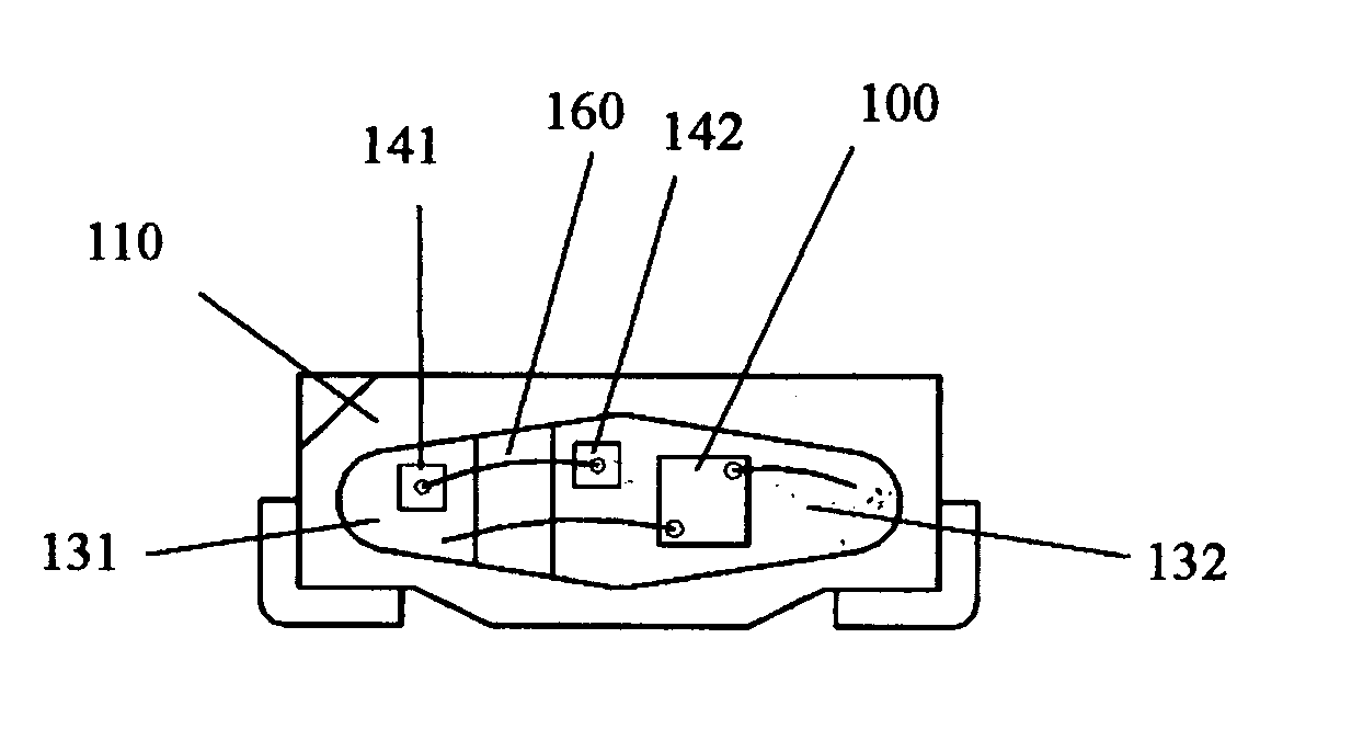
[0025] the present invention is shown in FIG 5. It shows the improvement over FIG. 1. A blue LED chip 100 is mounted on a negative lead frame 132, which is supported on a reflecting plate 110 as a structure. One of the top electrodes of the LED chip 100 is wire bonded to the negative lead frame 132, which is also supported on the substrate 110, and another top electrode of the LED 100 is wire bonded to the positive lead frame 131. Over the negative lead frame 132 is attached a p-type Zener diode chip 141 with silver paste, having a breakdown voltage of 6 V. Over the positive lead frame 131 is another p-type Zener diode chip 142 with silver paste having a breakdown voltage of 12 V. The two Zener diodes are connected back-to-back to each other using gold or aluminum bonding wires 160 to the bonding pads. The devices are then covered silicones with added phosphorescent powder to produce white light. The substrate can be printed circuit board, a ceramic or silicon composite

[0026]FIG. 6 ...

third embodiment

[0029]FIG. 9 show the invention. A blue LED 100 is mounted over a heat sink 180 and wrapped over by a plastic shell 115, which forms a unitary structure with the bottom of the heat sink exposed. The LED chip 100 is attached to the heat sink and is wire bonded with gold or aluminum wires to respective positive and negative lead flames 130. An n-type Zener diode 145 with a breakdown voltage of 5V and a red LED 146 are also mounted on the heat sink 180. The red LED 145 is wire bonded to the positive lead flame with gold or aluminum wire and the Zener diode 145 is wire bonded to the negative lead frame. (How are LED 146 and Zener diode 145 connected? not shown) The equivalent circuit of the structure is shown at the bottom of FIG. 9. When the reverse voltage exceed 6V due to static electricity or other reason, the red LED 116 light up as a warming.

[0030] While the foregoing embodiments have only one light emitting diode, the protective schemes can also be applied a LED chip having a plu...


PUM


Abstract

A light emitting diode (LED) package is fabricated with protection circuit against static electricity. The protection circuit includes series connection of more than one Zener diodes which limit any voltage surge no higher than their breakdown voltage, and is connected in parallel with the LED chip. The breakdown voltage of the protection circuit in either direction is greater than the rated forward or reverse testing voltage. The series connection of the protection circuit can be made through printed circuit submount.

Description

BACKGROUND OF THE INVENTION [0001] 1. Filed of Invention [0002] This invention relates to light emitting diode (LED), in particular to protection circuit against static electricity in a LED package. [0003] 2. Brief Description of Prior Art [0004]FIG. 1 shows a traditional LED package. A LED chip 100 is mounted on a lead frame. The LED chip 100 is bonded with aluminum or gold wire 160 to respective positive lead frame 131 and negative lead frame 132 for electrical connection. The lead frames are covered and glued to a reflecting plate 110. The structure is then covered with transparent resin 150. For better protection and light emission, the LED chip is first covered with silicone. Phosphorescent powder may be added to the silicone and / or resin for a blue color LED to emit white light. Such a structure is widely used in cellular phone. [0005] Another widely used back light for cellular phones using LEDs is shown in FIG. 2. A LED chip 100 is mounted on a printed circuit board 120, and...

Claims


Application Information

Patent Timeline
Patent Type & Authority Applications(United States)
IPC IPC(8): H01L23/02H01L23/60H01L25/075H01L25/16H01L33/00
CPCH01L25/0753H01L25/167H01L2224/45144H01L2224/48137H01L2224/45124H01L2224/48227H01L2224/48091H01L2924/00014H01L2924/00
Inventor HSIN CHEN, CHEN-LUNHUNG, JUNG-HAO
Owner HSIN CHEN CHEN LUN
Why Eureka
Try Eureka