Light-emitting device

a technology of light-emitting devices and light-emitting lamps, which is applied in the direction of semiconductor devices for light sources, lighting and heating apparatus, and lighting support devices, etc., can solve the problems of affecting the eyesight of users, mercury elements inside fluorescent lamps may be harmful to the human body, and pollute the environment, so as to achieve the effect of large total light throughput and even light emission

Inactive Publication Date: 2008-02-19
GRAND HALO TECH
View PDF12 Cites 128 Cited by
  • Summary
  • Abstract
  • Description
  • Claims
  • Application Information

AI Technical Summary

Benefits of technology

[0011]In the light of forgoing drawbacks, an objective of the present invention is to provide a light-emitting device having a large total light throughput and even light emission.
[0012]Another objective of the present invention is to provide a light-emitting device having heat-and electricity separation to reduce heat dissipation while providing protection.
[0013]Still another objective of the present invention is to provide a light-emitting device having a long rated life.
[0014]Yet another objective of the present invention is to provide a light-emitting device that can be easily assembled and disassembled.
[0015]Still another objective of the present invention is to provide a light-emitting device with high reliability.

Problems solved by technology

Since light source provided by this kind of illumination varies with AC current, flickering of the light source may directly affect the users' eyesight.
Additionally, the mercury element inside the fluorescent lamps may be harmful to the human bodies.
Disposing of the fluorescent lamps may also pollute the environment.
However, in the abovementioned techniques, the total light throughput is small due to the above structures being limited to dispose only one or a limited number of LEDs.
Moreover, TW Utility Model Pat. No. M286898 and M284176 do not provide any heat dissipating mechanism, the life of the LEDs are reduced due to large heat emission.
Although TW Utility Model Pat. No. M285658 incorporates a heat dissipating board, but current goes through the heat dissipating board, i.e. the driving circuit closely abuts the heat dissipating system, which may result in heat loss due to concentrated heat source.
This causes loss of optical energy and affects the reliability of the lighting.
Furthermore, the above patents lack an over-voltage protection design.
Accordingly, in a fixed-current mode, voltage cannot be stabilized at an operating range since the LED driving element cannot provide the over-voltage protection design.
In addition, TW Utility Model Pat. No. M286898 and M284176 do not provide a LED structure that can be easily assembled or disassembled.
While only a single LED can be provided in TW Utility Model Pat. No. M285658, the whole lighting fixture needs to be decomposed during assembly or disassembly, so the problem regarding assembly and disassembly still exists.

Method used


Image

  • Light-emitting device
  • Light-emitting device
  • Light-emitting device

Examples


first embodiment

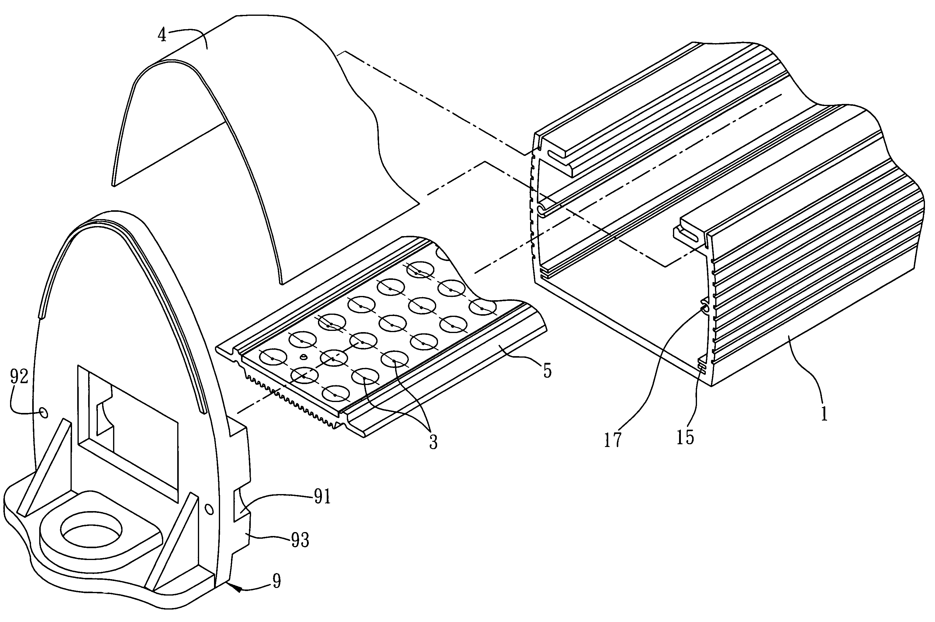
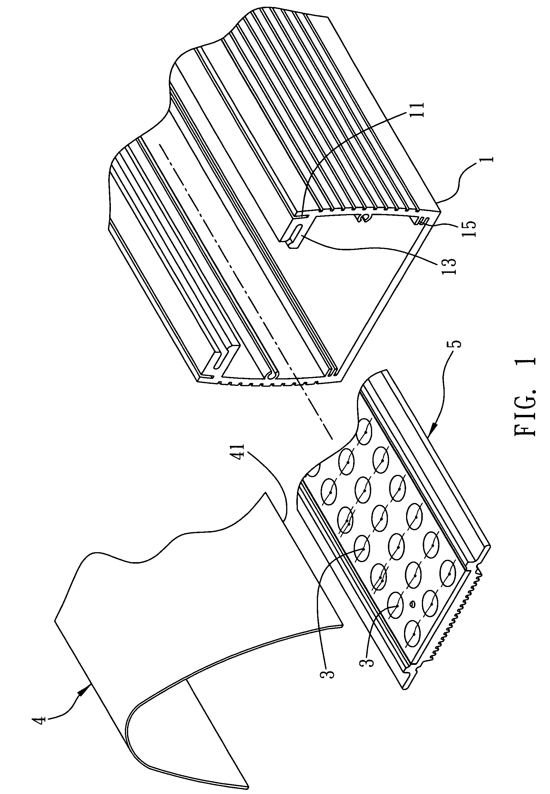
[0030]FIGS. 1 to 5 are diagrams depicting a first embodiment of the light-emitting device of the present invention. Referring to FIG. 1, an exploded diagram of the first embodiment of the light-emitting device of the present invention is shown. The light-emitting device of the present invention comprises a body 1, a plurality of light-emitting elements 3 at a side of the body 1 and an optical processing element 4 at a side of the light-emitting elements 3.

[0031]A first joining part 11 is provided at a side of the body 1 for joining with the optical processing element 4. In this embodiment, the body is a hollow frame and the first joining part 11 can, for example, be a track. Meanwhile, the body 1 further comprises a third joining part 13 that can also be, for example, a track. The third joining part 13 is substantially perpendicular to the first joining part 11.

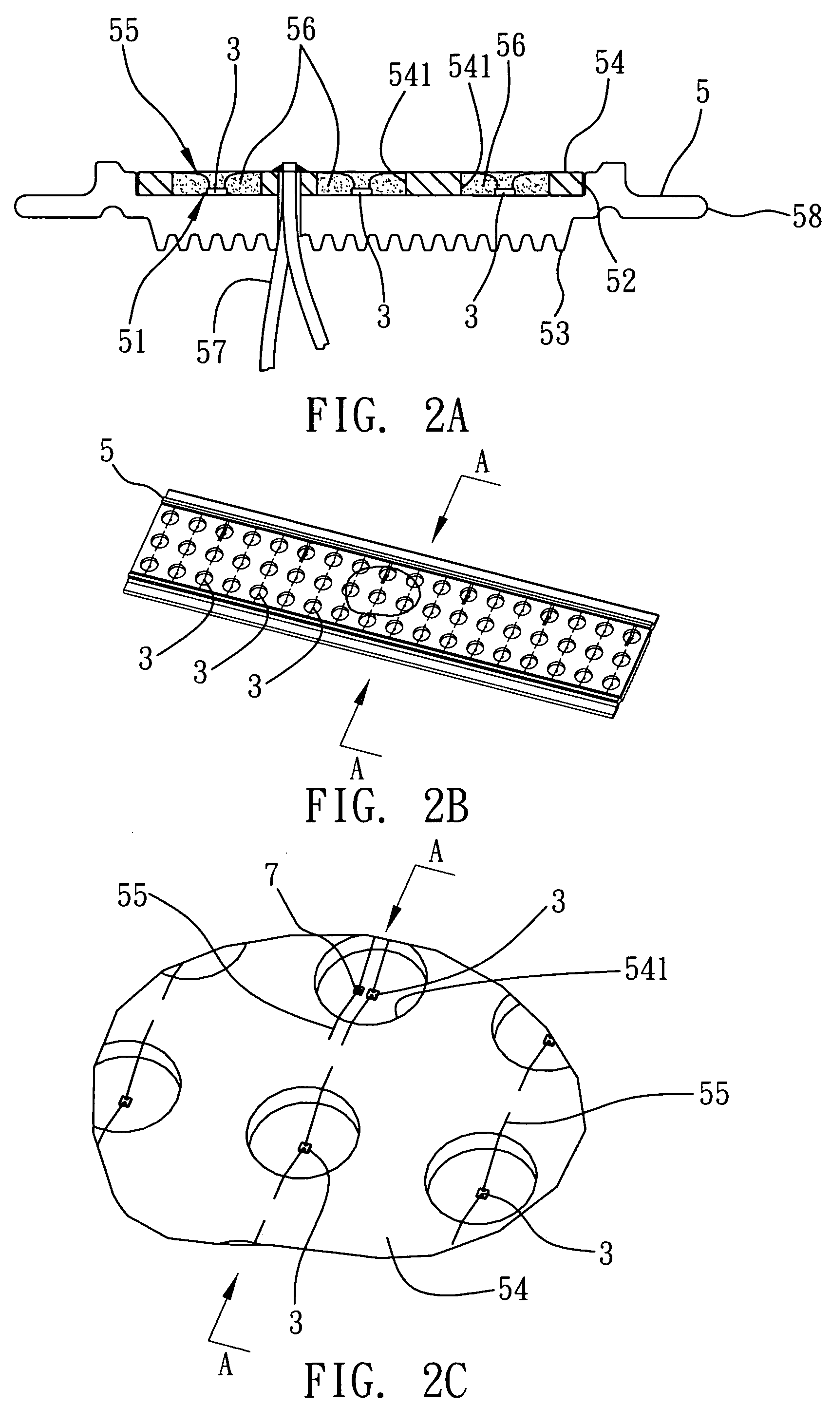
[0032]The light-emitting elements 3 are disposed at the side of the body having the first joining part 11 for emitting ligh...

second embodiment

[0042]FIGS. 6 and 7 are diagrams depicting a second embodiment of the light-emitting device of the present invention. Elements that are similar or equal to those shown in the first embodiment are denoted with similar to equal reference numbers, and their description are omitted in order not to obscure the understanding of the present invention.

[0043]The main difference of the present embodiment and the second embodiment is that a fastening element is added in the present embodiment.

[0044]As shown in FIG. 6, the body1 further comprises a seventh joining portion 17, such as a track. A fastening element 9 is disposed at one side of the body 1, which can be an end cap, for example. The fastening element 9 comprises an eighth joining portion 91 corresponding to the seventh joining portion 17, a through hole 92 in the eighth joining portion 91 and a ninth joining portion 93 located next to the eighth joining portion 91. The eighth joining portion 91 is, for example, an arc indentation to ...


PUM


Abstract

A light emitting device is disclosed, in which a body is provided with a first joining portion, light-emitting elements located at a side of the body having the first joining portion for emitting light and an optical processing element disposed at a side of the light-emitting elements having a second joining portion corresponding to the first joining portion for processing light emitted from each light-emitting element, such that even light emission is obtained.

Description

FIELD OF THE INVENTION [0001]The present invention relates to an illuminating technique, and more particularly, to a light-emitting device with a plurality of light-emitting elements.BACKGROUND OF THE INVENTION[0002]Traditional illumination usually uses fluorescent lamps as the light source, which allows high speed electrons in argon or neon gas to excite mercury by collision to produce ultraviolet light. The ultraviolet, when strikes a phosphor powder coated in the lamps, emits visible fluorescence for illumination. Since light source provided by this kind of illumination varies with AC current, flickering of the light source may directly affect the users' eyesight. Additionally, the mercury element inside the fluorescent lamps may be harmful to the human bodies. Disposing of the fluorescent lamps may also pollute the environment. Furthermore, applications of this type of lightings require electronic ballast or high-frequency inverter. It also has the shortcomings of slow starting,...

Claims


Application Information

Patent Timeline
Patent Type & Authority Patents(United States)
IPC IPC(8): F21V1/00F21K99/00H05B44/00
CPCF21V15/015F21V29/004F21V29/89F21V29/74F21V3/02F21Y2105/001F21V23/023F21Y2101/02F21Y2105/10F21Y2115/10F21V19/001
Inventor CHEN, HAI-HAN
Owner GRAND HALO TECH
Why Eureka
Try Eureka