Spectrometer arrangement

a technology of spectrometers and assemblies, applied in the direction of spectrometry/spectrophotometry/monochromators, instruments, optical radiation measurement, etc., can solve the problem of limited light throughput of such spectrometers with assemblies with internal separation of orders, and achieve high light throughput, small band width, and small volume

Active Publication Date: 2012-10-18
LEIBNIZ - INSTITUT FUER ANALYTISCHE WISSENSCHAFTEN ISAS
View PDF1 Cites 23 Cited by
  • Summary
  • Abstract
  • Description
  • Claims
  • Application Information

AI Technical Summary

Benefits of technology

[0034]The assembly according to the invention provides in a preferred embodiment of the invention an intensive, monochromatic light source with small band width with very high light throughput if illuminated with a continuum light source. The use of an assembly with a continuum light source and spectrometer enables the tuning over the entire wavelength range without having to change the light source.
[0035]In a preferred embodiment of the invention the above described assembly is used for the analysis in VUV-range. This is promoted by the small size of the volume which must be evacuated and minimum losses with few reflections and high transmission.

Problems solved by technology

It is disadvantageous however, that the light throughput of such spectrometers with assemblies with internal separation of the orders is limited to a large extent.

Method used


Image

  • Spectrometer arrangement
  • Spectrometer arrangement
  • Spectrometer arrangement

Examples


Embodiment Construction

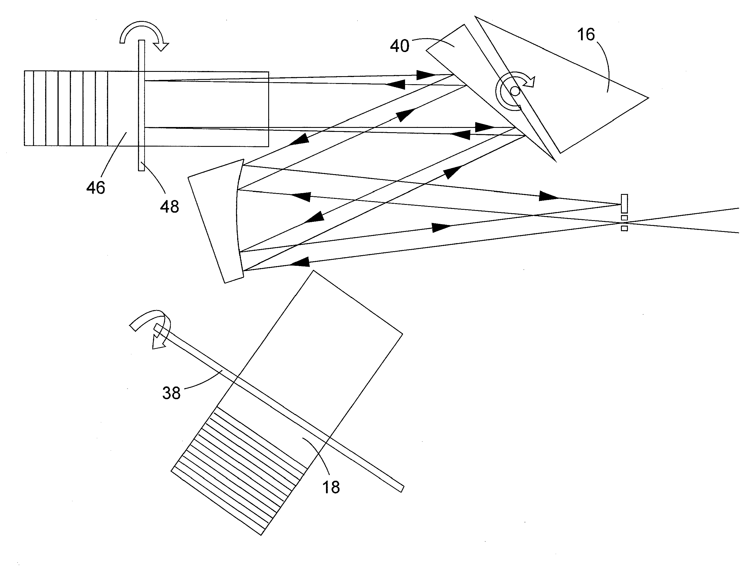
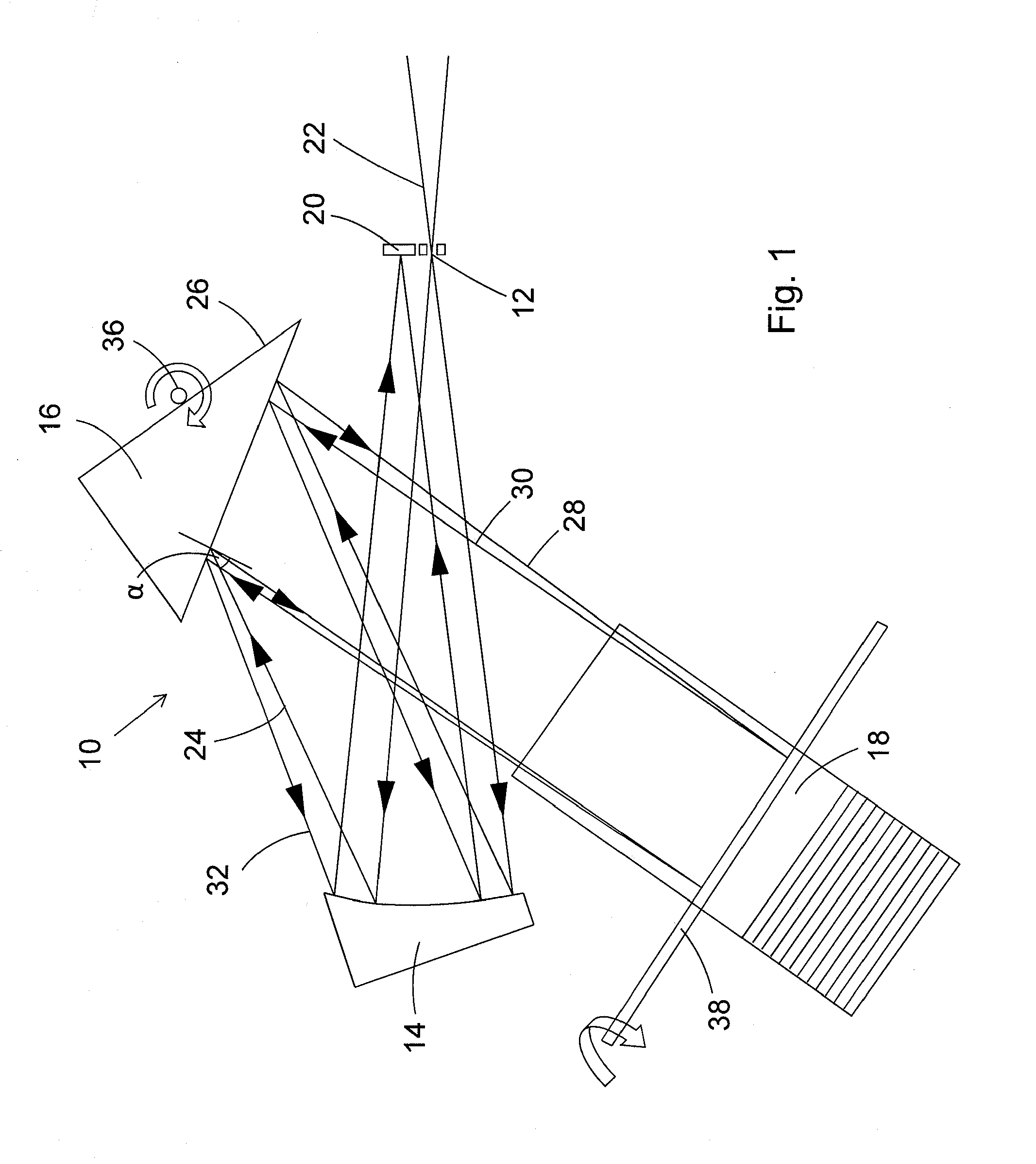
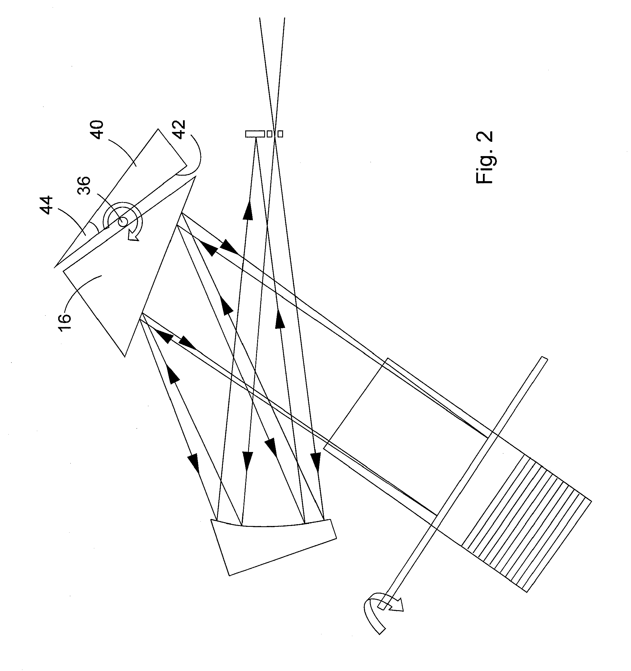
[0051]FIG. 1 is a schematic representation of a particularly simple spectrometer assembly which is generally denoted with numeral 10. The spectrometer assembly comprises an entrance slit 12, an off-axis paraboloid used as a collimator mirror 14, a prism 16 which is reflecting at its rear side, and an Echelle grating 18. A detector 20 is provided in the exit plane of the spectrometer assembly 10 for detecting the generated spectra. The roof edge of the prism 16 extends perpendicular to the representation plane. The grooves of the Echelle grating 18 run in the representation plane.

[0052]In addition to the above mentioned, optical components the spectrometer assembly 10 comprises further components, such as a housing, a base plate, fixing- and adjusting means, mechanical drivers and electrical components for controlling the optical components and for detecting and evaluating the signals at the detector 20, such components, however, not being shown for simplicity.

[0053]Radiation from a ...


PUM


Abstract

A spectrometer assembly (10), comprising an Echelle grating (18; 46) for dispersing radiation entering the spectrometer assembly (10) in a main dispersion direction, and a dispersion assembly (16; 40) for dispersing a parallel radiation bundle generated from the radiation entering the spectrometer assembly in a lateral dispersion direction, is characterized in that the dispersion assembly (16; 40) is reflective, and the dispersion assembly (16; 40) is arranged relative to the Echelle grating (18; 46) in such a way that the parallel radiation bundle is reflected in the direction of the Echelle grating. The Echelle grating (18; 46) may be arranged in such a way that the dispersed radiation is reflected back to the dispersion assembly (16; 40).

Description

TECHNICAL FIELD[0001]The invention relates to a spectrometer assembly, comprising:[0002](a) an Echelle grating for dispersing radiation entering the spectrometer assembly (10) in a main dispersion direction, and[0003](b) a dispersion assembly for dispersing a parallel radiation bundle generated from the radiation entering the spectrometer assembly in a lateral dispersion direction.[0004]The invention further relates to a method for spectrally dispersing radiation comprising the steps of:[0005](a) Generating a parallel radiation bundle;[0006](b) Dispersing the radiation with an Echelle grating in a main dispersion direction; and[0007](c) Dispersing the parallel radiation with a dispersing assembly in a lateral dispersion direction.[0008]In an Echelle spectrometer a grating with step-like cross section is used (Echelle (french)=stairs). Due to the step-like structure with a corresponding Blaze angle a diffraction pattern is generated which concentrates the diffracted radiation in high...

Claims


Application Information

Patent Timeline
Patent Type & Authority Applications(United States)
IPC IPC(8): G01J3/42
CPCG01J3/02G01J3/0208G01J3/021G01J2003/1828G01J3/14G01J3/1809G01J3/2803G01J3/0235
Inventor FLOREK, STEFANOKRUSS, MICHAELBECKER-ROSS, HELMUT
Owner LEIBNIZ - INSTITUT FUER ANALYTISCHE WISSENSCHAFTEN ISAS
Why Eureka
Try Eureka