Seal apparatus for circuit breaker application

a circuit breaker and sealing technology, applied in mechanical devices, non-enclosed substations, substations, etc., can solve problems such as unfavorable protection, electrical arcing, undesirable arcing, etc., and achieve the effect of improving the protection level

Active Publication Date: 2011-05-31
EATON INTELLIGENT POWER LTD
View PDF6 Cites 40 Cited by
  • Summary
  • Abstract
  • Description
  • Claims
  • Application Information

AI Technical Summary

Benefits of technology

[0010]Accordingly, an aspect of the invention is to provide an improved seal apparatus that resists the flow of exhaust gases and other matter between the interior regions of a switchgear cabinet and the exterior thereof during an arcing situation.
[0011]Another aspect of the invention is to provide an improved seal apparatus that provides an improved level of protection for an operator and other personnel in an arcing situation during racking and unracking operations.

Problems solved by technology

While such draw-out switchgear cabinets and circuit breakers have been generally effective for their intended uses, they have not been without limitation.
Such electrical arcing can occur, however, in a situation where a fault exists within the circuit breaker, for example, or in other circumstances.
Such arcing is undesirable because the explosive energy that is released can be dangerous to an operator and can be destructive of the switchgear equipment.
Such circuit breaker faults and other conditions are known to exist, and thus the potential for undesirable arcs within a switchgear cabinet remains.

Method used


Image

  • Seal apparatus for circuit breaker application
  • Seal apparatus for circuit breaker application
  • Seal apparatus for circuit breaker application

Examples


Embodiment Construction

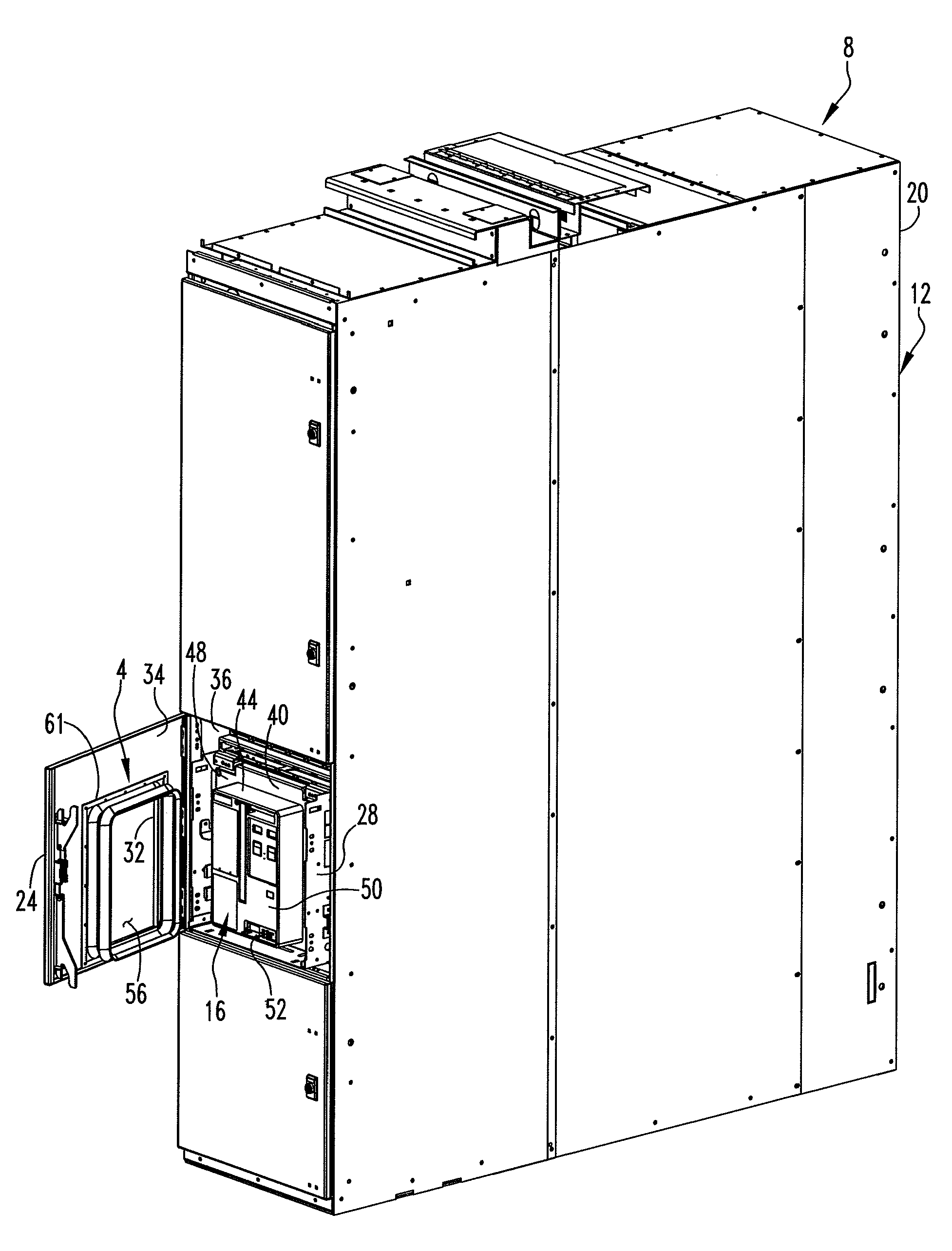
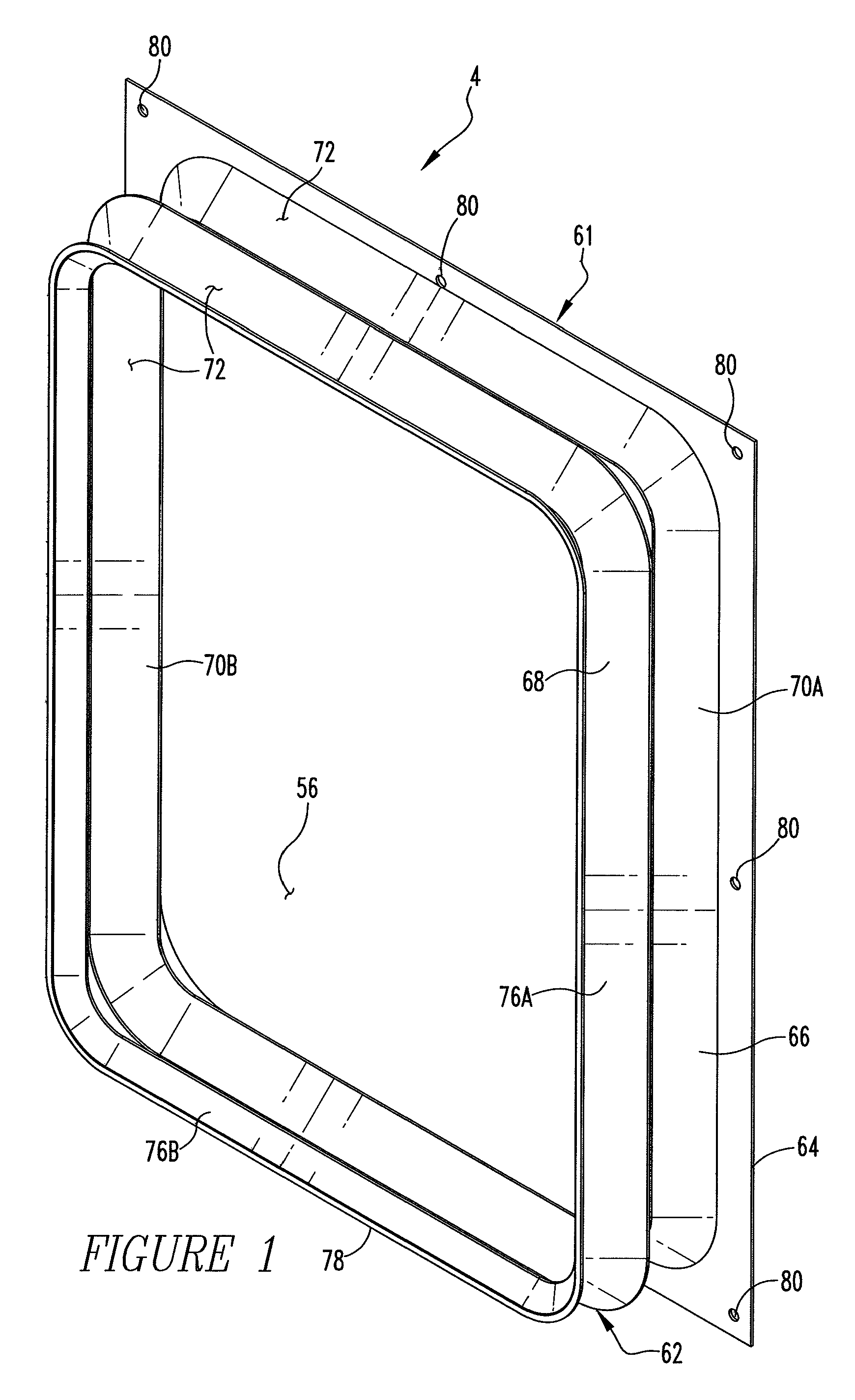
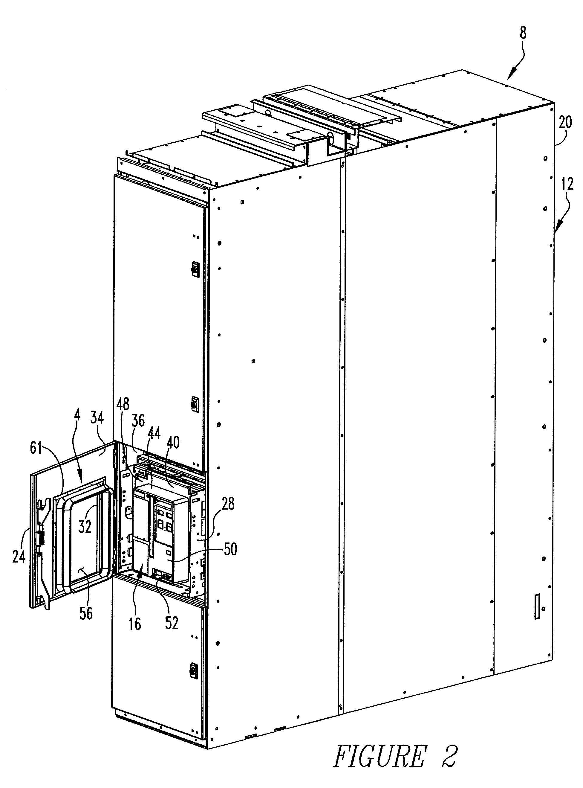
[0025]An improved seal apparatus 4 in accordance with the invention is depicted in FIGS. 1 and 2 and is depicted in section in FIGS. 5 and 6. The seal apparatus 4 can be advantageously incorporated into an improved switchgear apparatus 8 in accordance with the invention, as is depicted in FIG. 2.

[0026]The exemplary switchgear apparatus 8 is in the nature of draw-out circuit breaker equipment and includes a switchgear cabinet 12, a circuit breaker 16, and the seal apparatus 4. The switchgear cabinet 12 can be generally stated as including an enclosure 20 to which is mounted a door 24. The enclosure 20 has left, right, top, bottom, and rear walls connected together. The door 24 is movable between an open position, such as is depicted generally in FIG. 2, and a closed position, such as is depicted generally in FIGS. 3 and 4.

[0027]The switchgear cabinet 12 also includes a cassette 28 that is disposed on the enclosure 20. The circuit breaker 16 is mounted on the cassette 28, and the cass...


PUM


Abstract

A seal apparatus is disposed between a switchgear cabinet and a circuit breaker between the racked and unracked positions of the circuit breaker. The seal apparatus sealingly extends between the switchgear cabinet and the circuit breaker to resist fluid flow, such as exhaust gases and other matter, between an interior region of the switchgear cabinet and the exterior of the switchgear cabinet.

Description

BACKGROUND OF THE INVENTION[0001]1. Field of the Invention[0002]The invention relates generally to circuit breakers and, more particularly, to a seal apparatus that is employable in a circuit breaker application.[0003]2. Description of the Related Art[0004]Circuit breakers are generally well known and are used in numerous applications. For example, circuit breakers can be used to interrupt a circuit under one or more predetermined circumstances, and can be used for other purposes.[0005]Certain types of circuit breakers are mounted in switchgear cabinets during ordinary usage. A typical switchgear cabinet may have a number of electrical conductors which terminate at stabs that are disposed within an interior region of the switchgear cabinet. A switchgear cabinet that is employed with draw-out circuit breaker equipment may also include a slidable cassette within which a circuit breaker is mounted and which enables the circuit breaker to be movably disposed on the switchgear cabinet. S...

Claims


Application Information

Patent Timeline
Patent Type & Authority Patents(United States)
IPC IPC(8): H01H9/04
CPCH02B11/02F16J3/041
Inventor COOMER, JARROD LYLEMETCALF, DAVID AARONFAIR, TIMOTHYABRAHAMSEN, MICHAEL HOWARDHRNCIR, DANIEL EDWARDMOORE, STANLEY ERVINROWELL, AMY WILCOX
Owner EATON INTELLIGENT POWER LTD
Why Eureka
Try Eureka