Planar light source unit and liquid crystal display device using the unit

a technology of liquid crystal display device and light source unit, which is applied in the direction of lighting device details, lighting and heating apparatus, instruments, etc., can solve the problems of difficult disengagement, increase in the thickness of the planar light source unit or liquid crystal display device as a whole, and inability to achieve satisfactory effects, etc., to achieve excellent dimensional stability and stable assembling of metal frames

Active Publication Date: 2007-10-18
JAPAN DISPLAY CENTRAL CO LTD
View PDF3 Cites 13 Cited by
  • Summary
  • Abstract
  • Description
  • Claims
  • Application Information

AI Technical Summary

Benefits of technology

[0015] According to the present invention, it is possible to stably assemble the metal frame and plastic frame without inducing the disengagement thereof, enabling the provision of an inexpensive, thin planar light source unit or liquid crystal display device excellent in dimensional stability.

Problems solved by technology

With this, the plastic frame is positioned in a state of substantially no clearance between the metal frame and the plastic frame (in a state wherein the outer peripheral surface of the plastic frame is in contact with the inner peripheral surface of the metal frame) to make it difficult to induce the disengagement.
In this case, however, a satisfactory effect cannot be obtained when the metal frame has a small thickness.
Even slight gap, if any, will possibly result in disengagement similarly to the case of the mere fitting at the side surface alone.
In this case, however, the projections of the plastic frame will bulge out from the metal frame, resulting in an increase in thickness of the planar light source unit or liquid crystal display device as a whole.

Method used


Image

  • Planar light source unit and liquid crystal display device using the unit
  • Planar light source unit and liquid crystal display device using the unit
  • Planar light source unit and liquid crystal display device using the unit

Examples


Embodiment Construction

[0024] The planar light source unit and liquid crystal display device according to the present invention will be described hereinafter with reference to the accompanying drawings.

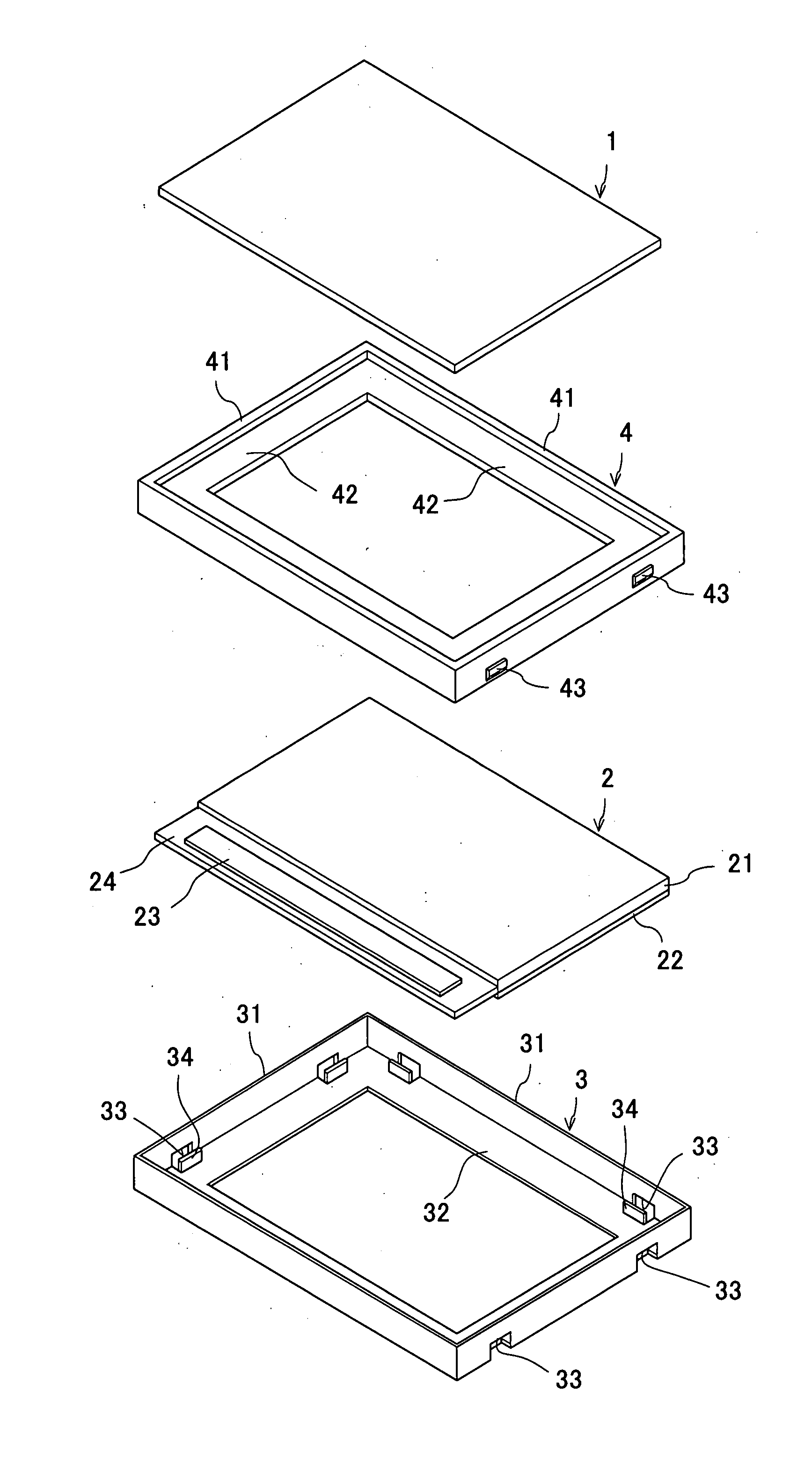
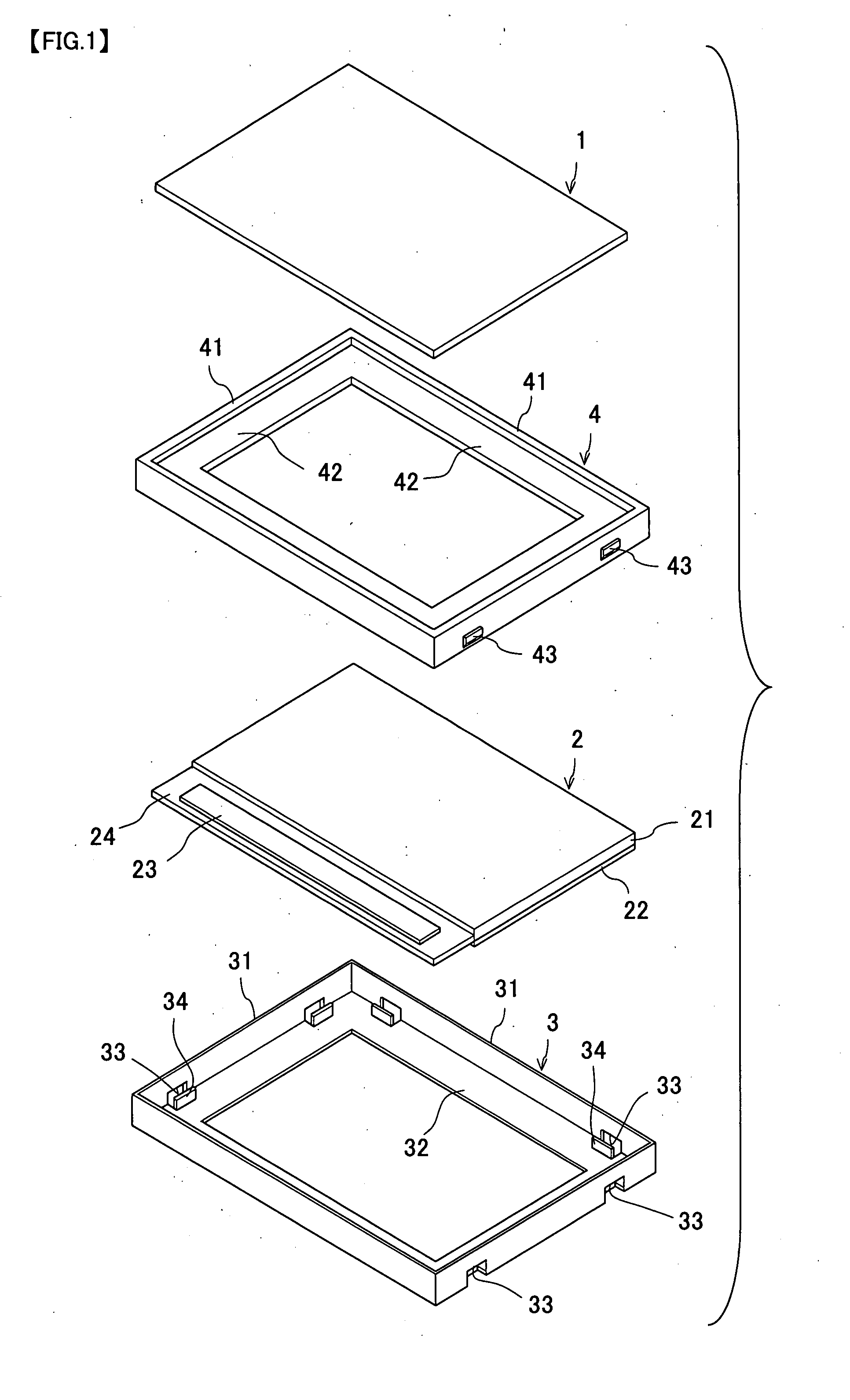
[0025]FIG. 1 is an exploded perspective view showing a liquid crystal display device having a planar light source unit incorporated into it. The liquid crystal display device of this embodiment is provided, as shown in FIG. 1, with a liquid crystal display panel 1 and a light source panel 2 that are retained with a combination of a metal frame 3 and a plastic frame 4.

[0026] The liquid crystal display panel 1 comprises an array substrate, an opposed substrate and a liquid crystal material inserted between the two substrates, for example. The array substrate is formed with pixel electrodes corresponding to display pixels and a switching device (thin-film transistor) in matrix form. Also, on the liquid crystal panel 1, signal lines for transmitting signals to the pixel electrodes and gate lines for transmitt...


PUM


Abstract

A planar light source unit includes a metal frame retaining a light source panel provided with an light guide for inducing emission of light from a light source and a plastic frame that supports at least part of a peripheral edge of the light guide. The outer peripheral surface of the plastic frame with a fitting structure between the metal frame and the plastic frame and an outer frame portion contiguous to the support plate portion and sandwiched between the fixing means and the outer frame portion of the metal frame. A liquid crystal display panel is provided with a display region in which plural display pixels are arrayed and the planar light source unit.

Description

BACKGROUND OF THE INVENTION [0001] 1. Field of the Invention [0002] The present invention relates to a planar light source unit used in a liquid crystal display device, for example, and to a liquid crystal display device using the planar light source unit. [0003] 2. Description of the Related Art [0004] In recently years, as display devices for information technology (IT) devices including personal computers, word processors, etc. and for video equipment including television sets, camcorders, car navigation systems, etc., liquid crystal display devices having lightweight, thin-shaped and low-power-consumption properties have been in heavy usage. Major ones of these liquid crystal display devices have a configuration provided with a built-in lighting unit (planar light source unit) for emitting light from behind a liquid crystal panel in order to realize a bright display screen. [0005] The lighting unit is classified into an edge light type lighting unit and a direct light type light...

Claims


Application Information

Patent Timeline
Patent Type & Authority Applications(United States)
IPC IPC(8): F21V7/04
CPCG02B6/0088
Inventor IDA, KAZUSHIGE
Owner JAPAN DISPLAY CENTRAL CO LTD
Why Eureka
Try Eureka