Ceramic heater

a ceramic heater and heater body technology, applied in the field of ceramic heaters, can solve the problem of insufficient thermal uniformity and other problems

Pending Publication Date: 2021-07-29
NGK INSULATORS LTD
View PDF0 Cites 1 Cited by
  • Summary
  • Abstract
  • Description
  • Claims
  • Application Information

AI Technical Summary

Benefits of technology

[0012]In the ceramic heater according to the present invention, the ceramic plate may have a hole that extends therethrough in a vertical direction, and the sub resistance heating element may be disposed around the hole. The main resistance heating element is wired so as to detour around the hole that extends through the ceramic plate in the vertical direction. For this reason, a portion around the hole is likely to have the temperature singularity. The sub resistance heating element is disposed around the hole here, and the portion around the hole can be prevented from having the temperature singularity.
[0013]In the ceramic heater according to the present invention, the main resistance heating element may extend from the one of the pair of main terminals, may be folded at folded portions, and may reach the other of the pair of main terminals, and the sub resistance heating element may be disposed at a portion at which the folded portions

Problems solved by technology

For this reason, there is a problem in that su

Method used


Image

  • Ceramic heater
  • Ceramic heater
  • Ceramic heater

Examples


Embodiment Construction

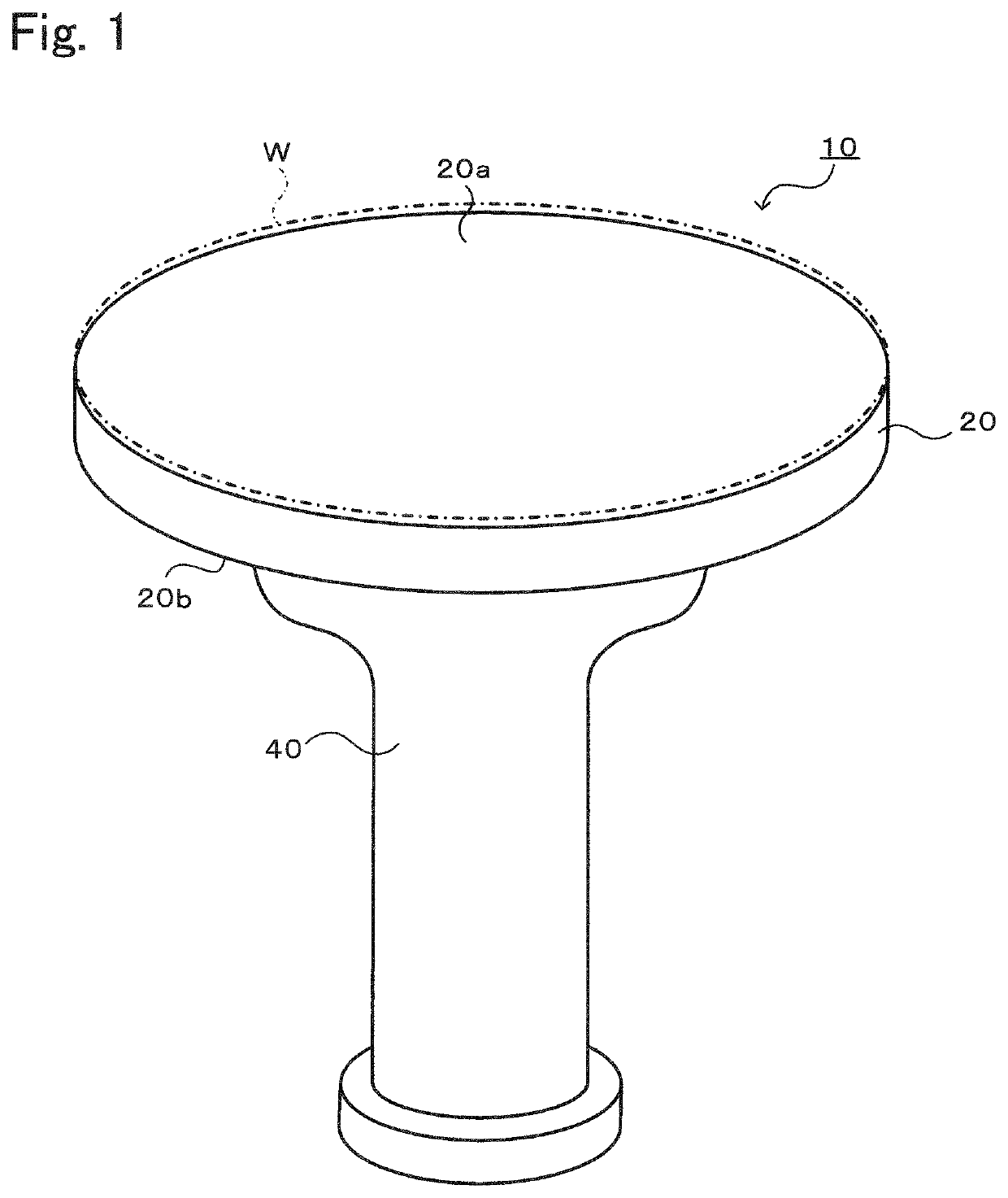
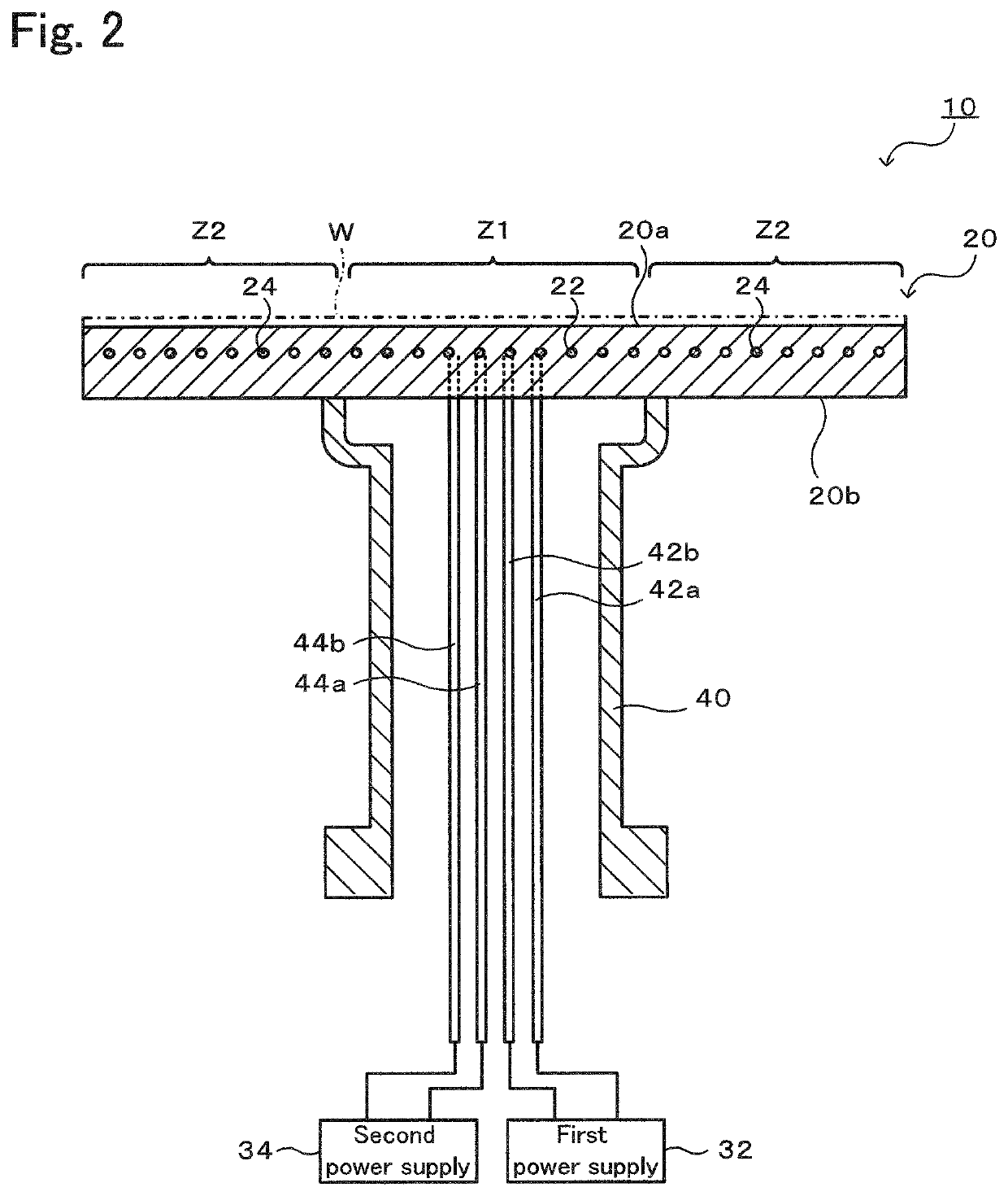
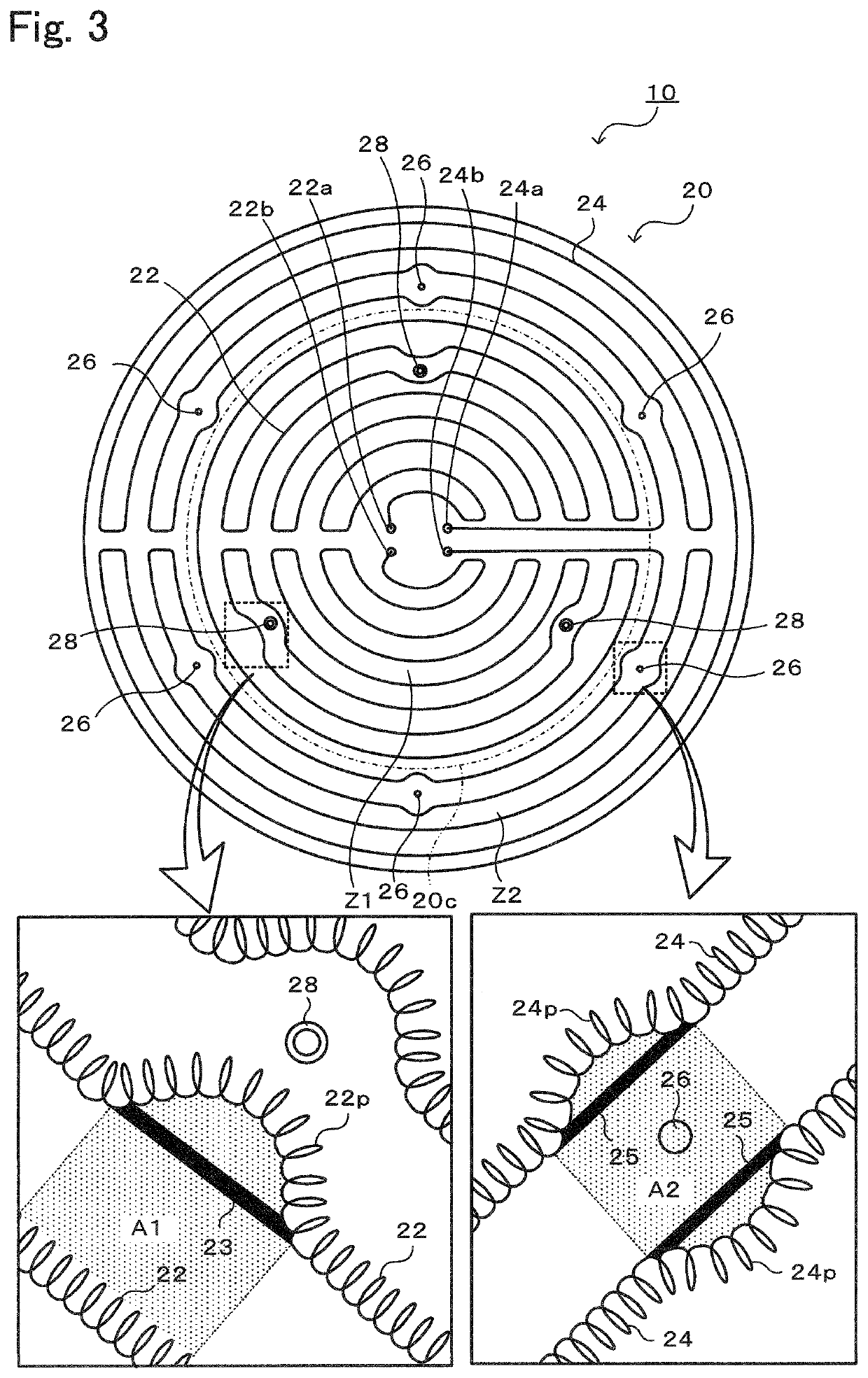
[0026]A preferred embodiment of the present invention will hereinafter be described with reference to the drawings. FIG. 1 is a perspective view of a ceramic heater 10 according to a first embodiment. FIG. 2 is a longitudinal sectional view (a sectional view of the ceramic heater 10 taken along a plane containing a central axis) of the ceramic heater 10. FIG. 3 is a sectional view of a ceramic plate 20 taken along a plane parallel with resistance heating elements 22 and 24 and viewed from above. FIG. 3 illustrates the ceramic plate 20 substantially viewed from a wafer placement surface 20a. In FIG. 3, hatching representing a section is omitted.

[0027]The ceramic heater 10 is used to heat a wafer that is subjected to a process such as etching or CVD and is installed in a vacuum chamber not illustrated. The ceramic heater 10 includes the ceramic plate 20 that has the wafer placement surface 20a and that is discoid, and a tubular shaft 40 that is joined coaxially with the ceramic plate ...


PUM


Abstract

A ceramic heater includes a ceramic plate, a main resistance heating element, and a sub resistance heating element. The main resistance heating element is a coil that is disposed in the ceramic plate, that is wired from one of a pair of main terminals in a one-stroke pattern, and that reaches the other of the pair of the main terminals. The sub resistance heating element is a heating element that is disposed in the ceramic plate, that complements heating with the main resistance heating element, and that has a two-dimensional shape.

Description

BACKGROUND OF THE INVENTION1. Field of the Invention[0001]The present invention relates to a ceramic heater.2. Description of the Related Art[0002]For a semiconductor-manufacturing apparatus, a ceramic heater that heats a wafer is used. A so-called two-zone heater is known as such a ceramic heater. In a heater known as this kind of two-zone heater, as disclosed in PTL 1, an inner-peripheral resistance heating element and an outer-peripheral resistance heating element are embedded in a ceramic base on the same plane, and heat generated from the resistance heating elements is separately controlled by separately applying a voltage to the resistance heating elements. Each resistance heating element is a coil composed of high-melting-point metal such as tungsten.CITATION LISTPatent Literature[0003]PTL 1: Japanese Patent No. 3897563 BSUMMARY OF THE INVENTION[0004]According to PTL 1, however, the resistance heating elements are the coils, and accordingly, the adjacent coils need to be spac...

Claims


Application Information

Patent Timeline
IPC IPC(8): H05B3/28H05B3/18H05B3/14
CPCH05B3/283H01L21/67103H05B3/14H05B3/18H05B3/143H05B3/12H01L21/68757
Inventor ISHIKAWA, MASAKIMOTOYAMA, SHUICHIRO
Owner NGK INSULATORS LTD
Why Eureka
Try Eureka