Micro-nozzle having an integrated filter

a technology of integrated filter and micro-nozzle, which is applied in the direction of filtration separation, filtration separation, and stationary filter element filters, can solve the problems of large system designed for better filtration, difficult to provide a compact nozzle and filter system with high quality filtration, and achieve the effect of reducing manufacturing costs and increasing filtering capacity

Pending Publication Date: 2022-01-06
TTP PLC
View PDF0 Cites 0 Cited by
  • Summary
  • Abstract
  • Description
  • Claims
  • Application Information

AI Technical Summary

Benefits of technology

[0008]The present invention provides a micro-nozzle with integrated filter structure, which combines the advantages of statistical and absolute filtering

Problems solved by technology

One of the key challenges in these systems is preventing the micro-nozzles from becoming blocked or obscured during operation.
Examples of contaminants which commonly cause obstruction of the nozzle include manufacturing debris, component wear, formulation precipitation and/or agglomerates in formulations comprising particle suspensions.
Any one of these factors could be a cause of a blocked nozzle during the life-cycle of an aerosol system.
However, the efficacy of such a filtration system is typically heavily dependent on the surface area availa

Method used


Image

  • Micro-nozzle having an integrated filter
  • Micro-nozzle having an integrated filter
  • Micro-nozzle having an integrated filter

Examples


Embodiment Construction

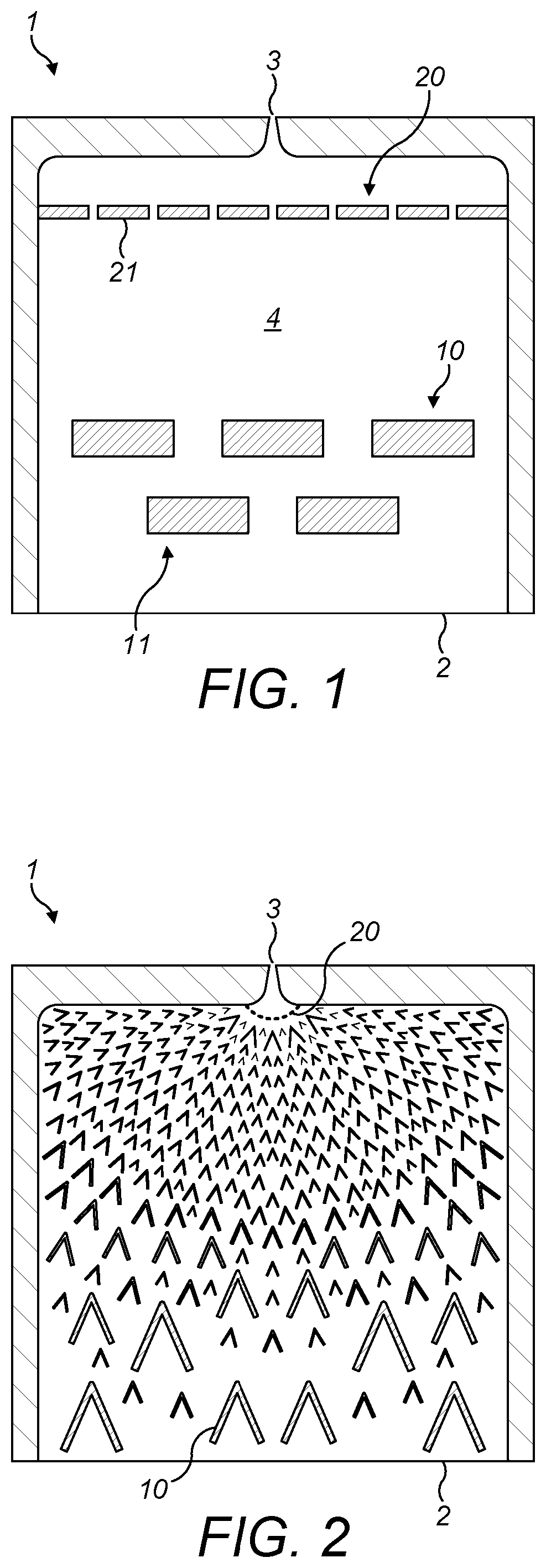
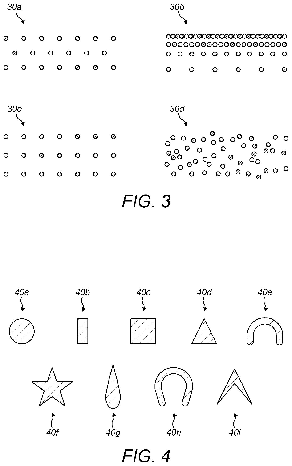
[0067]An example nozzle 1 is generally illustrated in an open configuration in FIG. 1. The nozzle 1, shown in FIG. 1 in a top-down view, comprises an inlet 2, an outlet 3 and a base surface 4. The nozzle also comprises a primary filter structure 10 and a secondary filter structure 20. Although FIG. 1 shows the nozzle 1 in an open configuration, the nozzle 1 is completed by covering the components shown with a cover surface, which matches the planar dimensions of the base surface 4 to form a fluid-tight volume.

[0068]The inlet 2 is arranged at one end of the nozzle 1, and comprises an opening to allow, in use, fluid to enter the nozzle 1. In this example, the inlet 2 is a multi-channel inlet. By ‘multi-channel’ we intend to mean that the inlet 2 comprises a one or more slots forming channels 2a. In other examples, the inlet 2 comprises a single aperture through which the fluid is arranged to flow in to the nozzle 1. In use, the multi-channel inlet 2 is arranged to receive fluid from a...


PUM

PropertyMeasurementUnit
Lengthaaaaaaaaaa
Lengthaaaaaaaaaa
Lengthaaaaaaaaaa

Abstract

A micro-nozzle with an integrated filter structure for receiving fluids at pressures between 0.1 MPa to 50 MPa, comprising: at least one fluid inlet, a fluid outlet comprising at least one orifice, a primary filter structure positioned downstream from the at least one fluid inlet and arranged to provide statistical filtration of fluid passing therethrough.

Description

RELATED APPLICATION[0001]The present application is a national stage application under 35 U.S.C. § 371 of International Application No. PCT / GB2019 / 052754, filed 30 Sep. 2019, which claims priority to Great Britain Patent Application No. 1815944.2, filed 28 Sep. 2018. The above referenced applications are hereby incorporated by reference.BACKGROUND[0002]The present invention relates to a nozzle for aerosol systems. In particular, the present invention relates to a micro-nozzle with an integrated filter for preventing obstruction of the nozzle by contaminants in a fluid being aerosolised.[0003]Mechanical systems for aerosolising fluids (typically liquids) are highly effective for delivering pharmaceutical ingredients to the lunge, nose, eyes, skin or mouth. The aerosols generated by such systems are generally monodisperse and more controllable than those produced by typical pump sprays. As such, delivery can be targeted with fast uptake while minimising undesirable effects such as unc...

Claims


Application Information

Patent Timeline
IPC IPC(8): B05B15/40B01D29/50
CPCB05B15/40B01D29/0004B01D29/50B01D45/08B01D29/01
Inventor GREENENKO, ALONPERDIGO-OLIVERAS, ARNAUCHEUNG, CHUNG MANSTRANGE, DANIEL GEOFFREY TYLERWANG, JIANYEKOHOUT, PAVELSELBY, ROBERT GORDON MAURICE
Owner TTP PLC
Why Eureka
Try Eureka