Process and plant for preparation of hydrogen and separation of carbon dioxide

a technology of carbon dioxide and process, which is applied in the direction of separation processes, lighting and heating apparatus, liquefaction, etc., can solve the problems of large carbon dioxide footprint of steam reforming process, inability to send carbon dioxide which is desorbed or separated out by condensation at low temperature at low temperature, and insufficient selectivity of membrane separation process in particular, so as to improve the thermal integration of the process and increase the carbon dioxide content. , the effect of high calorific valu

Active Publication Date: 2022-02-17
LAIR LIQUIDE SA POUR LETUDE & LEXPLOITATION DES PROCEDES GEORGES CLAUDE
View PDF2 Cites 1 Cited by
  • Summary
  • Abstract
  • Description
  • Claims
  • Application Information

AI Technical Summary

Benefits of technology

[0040]Alternatively, gases present in the hydrogen-rich stream HG2 are utilized as fuel gases for heating in the autothermal reforming step of step c). For the autothermal reforming step, the feed gas FG has to be warmed, which can be effected, for example, by means of a fired heating unit. The fired heating unit may be heated at least partly with the aid of the gases present in the hydrogen-rich stream HG2 that have a high calorific value, especially carbon monoxide, methane and hydrogen, in order to improve the thermal integration of the process.
[0041]A preferred embodiment of the process according to the invention is characterized in that the carbon dioxide-rich stream CG1 comprises unreacted methane, and the carbon dioxide-rich stream CG1 is subjected to a thermal separation process for separation of methane, giving a carbon dioxide-rich stream CG2. The carbon dioxide-rich stream may, as a result of...

Problems solved by technology

The steam reforming process has a large carbon dioxide footprint since about 9 tonnes of carbon dioxide are emitted for every tonne of hydrogen produced.
However, the carbon dioxide which is absorbed in absorbents in large volumes and then desorbed again or separated out by condensation at low temperatures frequently cannot be sent to any viable further industria...

Method used


Image

  • Process and plant for preparation of hydrogen and separation of carbon dioxide
  • Process and plant for preparation of hydrogen and separation of carbon dioxide
  • Process and plant for preparation of hydrogen and separation of carbon dioxide

Examples


Embodiment Construction

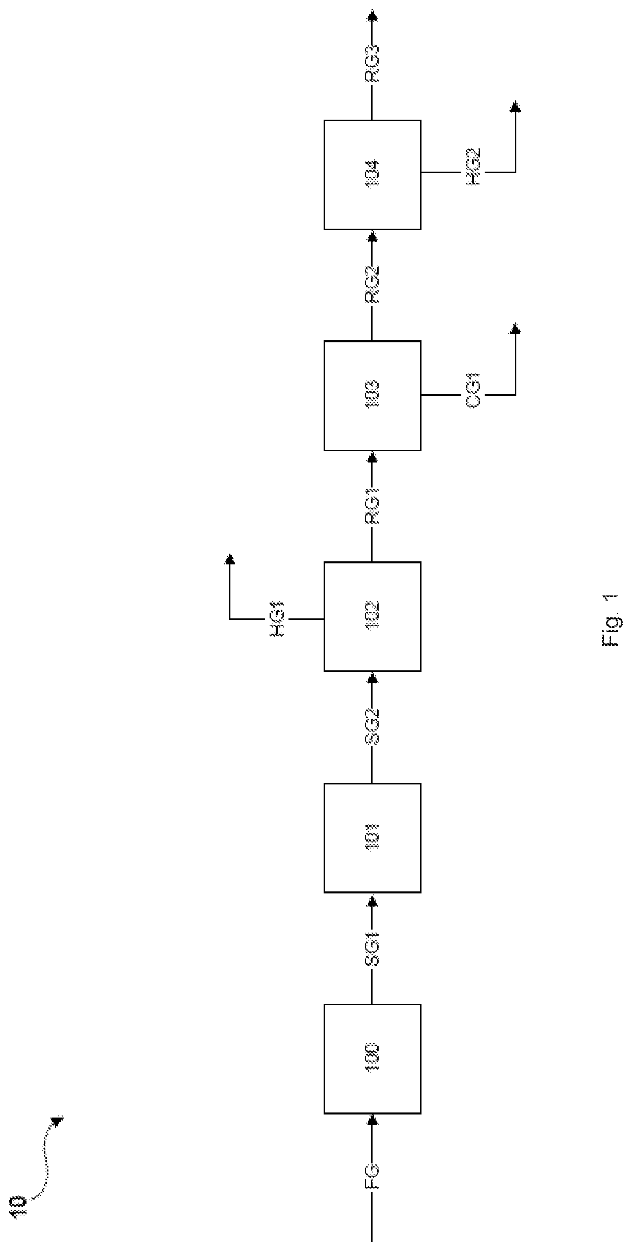
[0078]FIG. 1 shows a highly simplified block flow diagram of a process or plant according to the prior art, as disclosed, for example, in US 2015 / 0321914. A feed gas stream FG is introduced into an autothermal reforming unit 100 and converted to a synthesis gas stream SG1. Synthesis gas stream SG1 is subsequently introduced into a converter unit 101, which results in reaction of carbon monoxide present in synthesis gas stream SG1 with steam to give carbon dioxide and hydrogen. Hydrogen-enriched synthesis gas stream SG2 is subsequently introduced into a pressure swing adsorption unit 102 in order to separate hydrogen from the synthesis gas stream SG2 with high purity. Hydrogen separated from the pressure swing adsorption unit 102 is discharged from the pressure swing adsorption unit 102 in the form of a hydrogen-rich stream HG1. A hydrogen-depleted residual gas stream RG1 is likewise drawn off from the pressure swing adsorption unit 102 and introduced into a separation unit 103. In t...


PUM


Abstract

The invention relates to a process for preparing hydrogen by reforming hydrocarbons with steam, and for separation of carbon dioxide. The process includes one endothermic and one autothermal reforming step for production of a synthesis gas stream, wherein heat generated in the autothermal reforming step is utilized for heating in the endothermic reforming step. The process also includes a step of converting the synthesis gas stream obtained for enrichment with hydrogen, a step of separating the hydrogen thus prepared by pressure swing adsorption, and a step of separation of carbon dioxide from the residual gas obtained in the pressure swing adsorption. The reforming units for the endothermal and autothermal reforming steps are arranged parallel to one another or in series.

Description

CROSS REFERENCE TO RELATED APPLICATIONS[0001]This application claims priority to EP 20020366, filed Aug. 11, 2020, the entire contents of which are incorporated herein by reference.BACKGROUNDField of the Invention[0002]The invention relates to a process for preparing hydrogen by reforming hydrocarbons with steam, and for separation of carbon dioxide. The invention further relates to a plant for preparation of hydrogen by reforming hydrocarbons with steam, and for separation of carbon dioxide.Prior Art[0003]A current estimate of the volume of hydrogen produced globally is 70 Mt / a, with the greatest proportion thereof produced by endothermic reforming of natural gas with steam over a nickel-based reforming catalyst. In this process, referred to as steam methane reforming (SMR), there is reaction mainly of methane and steam to give a mixture of mainly hydrogen, carbon monoxide and carbon dioxide. The steam reforming process has a large carbon dioxide footprint since about 9 tonnes of c...

Claims


Application Information

Patent Timeline
IPC IPC(8): C01B3/40C01B3/48B01D53/047
CPCC01B3/40C01B3/48B01D53/047C01B2203/1241C01B2203/046C01B2203/1058C01B2203/042C01B2203/0244C01B2203/0405C01B2203/0233C01B3/38C01B3/56C01B3/506C01B3/503C01B32/50C01B2203/1235C01B2203/0261C01B2203/0811C01B2203/043C01B2203/0475C01B2203/0283C01B2203/147B01D53/002B01D2257/504B01D2256/16B01D53/22Y02C20/40Y02P20/151C01B3/382F25J3/067F25J3/08C01B2203/0838C01B2203/0833
Inventor SCHMIDT, SOPHIASCHMID MCGUIINESS, TEJA
Owner LAIR LIQUIDE SA POUR LETUDE & LEXPLOITATION DES PROCEDES GEORGES CLAUDE
Why Eureka
Try Eureka