Unlock instant, AI-driven research and patent intelligence for your innovation.

Moving picture coding device, moving picture coding method, moving picture coding program, moving picture decoding device, moving picture decoding method, and moving picture decoding program

a picture coding and picture technology, applied in the field of moving picture coding and decoding, can solve problems such as poor prediction efficiency, and achieve the effect of low load picture coding/decoding process and high efficiency

Pending Publication Date: 2022-04-07
JVC KENWOOD CORP A CORP OF JAPAN
View PDF0 Cites 0 Cited by
  • Summary
  • Abstract
  • Description
  • Claims
  • Application Information

AI Technical Summary

Benefits of technology

The invention allows for effective and low-load processing of pictures during coding and decoding. This results in higher efficiency.

Problems solved by technology

However, the technique of Patent Document 1 uses only the decoded samples in the neighbor of the coding / decoding target block, for prediction, and this results in poor prediction efficiency.

Method used


Image

  • Moving picture coding device, moving picture coding method, moving picture coding program, moving picture decoding device, moving picture decoding method, and moving picture decoding program
  • Moving picture coding device, moving picture coding method, moving picture coding program, moving picture decoding device, moving picture decoding method, and moving picture decoding program
  • Moving picture coding device, moving picture coding method, moving picture coding program, moving picture decoding device, moving picture decoding method, and moving picture decoding program

Examples


first embodiment

[0104]A picture coding device 100 and a picture decoding device 200 according to a first embodiment of the present invention will be described.

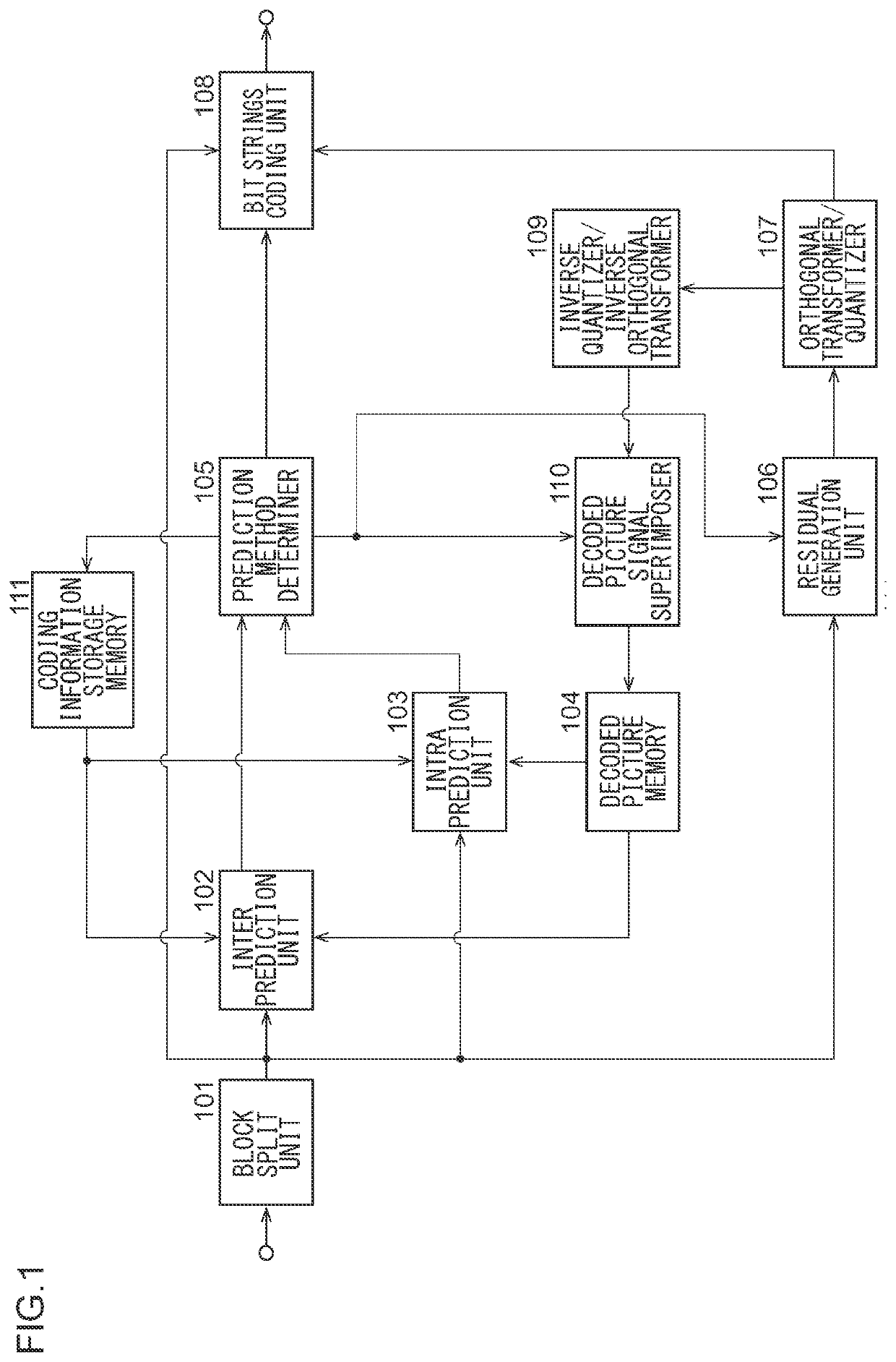
[0105]FIG. 1 is a block diagram of the picture coding device 100 according to the first embodiment. The picture coding device 100 according to an embodiment includes a block split unit 101, an inter prediction unit 102, an intra prediction unit 103, decoded picture memory 104, a prediction method determiner 105, a residual generation unit 106, an orthogonal transformer / quantizer 107, a bit strings coding unit 108, an inverse quantizer / inverse orthogonal transformer 109, a decoded picture signal superimposer 110, and coding information storage memory 111.

[0106]The block split unit 101 recursively splits an input picture to construct a coding block. The block split unit 101 includes: a quad split unit that splits a split target block in both the horizontal direction and the vertical direction; and a binary-ternary split unit that splits a split...


PUM


Abstract

A picture coding device includes: a block vector candidate derivation unit that derives block vector candidates of a target block in a target picture from coding information stored in coding information storage memory; a selector that selects a selected block vector from the block vector candidates; and a reference position correction unit that performs a correction regarding a reference block to be referred to by the selected block vector so that a reference position of the reference block is to be corrected to refer to an inside of a referenceable region, in which a decoded sample in the target picture is acquired from decoded picture memory as a prediction value of the target block based on the reference position of the reference block.

Description

BACKGROUND OF THE INVENTION1. Field of the Invention[0001]The present invention relates to picture coding and decoding techniques in which a picture is split into blocks and prediction is performed.2. Description of the Related Art[0002]In coding and decoding of a picture, a target picture is split into blocks, each of which being a group of a predetermined number of samples, and processing is performed in units of blocks. Splitting a picture into appropriate blocks with appropriate settings of intra prediction and inter prediction enables improvement of coding efficiency.[0003]Patent Document 1 discloses an intra prediction technique of obtaining a predicted picture by using decoded samples in the neighbor of a coding / decoding target block.PATENT LITERATURE[0004][Patent Literature 1] JP 2009-246975 ASUMMARY OF THE INVENTION[0005]However, the technique of Patent Document 1 uses only the decoded samples in the neighbor of the coding / decoding target block, for prediction, and this res...

Claims


Application Information

Patent Timeline
IPC IPC(8): H04N19/105H04N19/132H04N19/159H04N19/176
CPCH04N19/105H04N19/176H04N19/159H04N19/132H04N19/103H04N19/70H04N19/139H04N19/11H04N19/119H04N19/513H04N19/52H04N19/55H04N19/593H04N19/423
Inventor TAKEHARA, HIDEKINAKAMURA, HIROYASAKAZUME, SATORUFUKUSHIMA, SHIGERUKUMAKURA, TORUKURASHIGE, HIROYUKI
Owner JVC KENWOOD CORP A CORP OF JAPAN