Backlight module and display device

Active Publication Date: 2022-04-14
SHENZHEN CHINA STAR OPTOELECTRONICS SEMICON DISPLAY TECH CO LTD
View PDF0 Cites 0 Cited by
  • Summary
  • Abstract
  • Description
  • Claims
  • Application Information

AI Technical Summary

Benefits of technology

The present application provides a backlight module and display device. The backlight module includes a backlight source and a driving circuit for driving the backlight source. The driving circuit includes a data signal input module, a driving module, a storage module, and a compensation module. The compensation module is connected to the driving module and is configured to pull down the potential of a first node to be less than a potential of a second node during a blank frame phase to make the threshold voltage of the driving module negatively biased. This correction can alleviate the forward bias of the threshold voltage of the driving module, which results in a normal charging of the backlight unit and maintains brightness even after extended use.

Problems solved by technology

Conventional LEDs often use a driving circuit to emit light, but when the LEDs emit light for a long time, a threshold voltage of a driving transistor in the driving circuit is prone to forward bias, resulting in an insufficient charging of the LEDs, and brightness will decrease after a long light emission time, which will affect the display effect.
Therefore, the conventional LED backlight modules have a technical problem that brightness of the LEDs decreases after a long light emission time, and needs to be improved.

Method used


Image

  • Backlight module and display device
  • Backlight module and display device
  • Backlight module and display device

Examples


Embodiment Construction

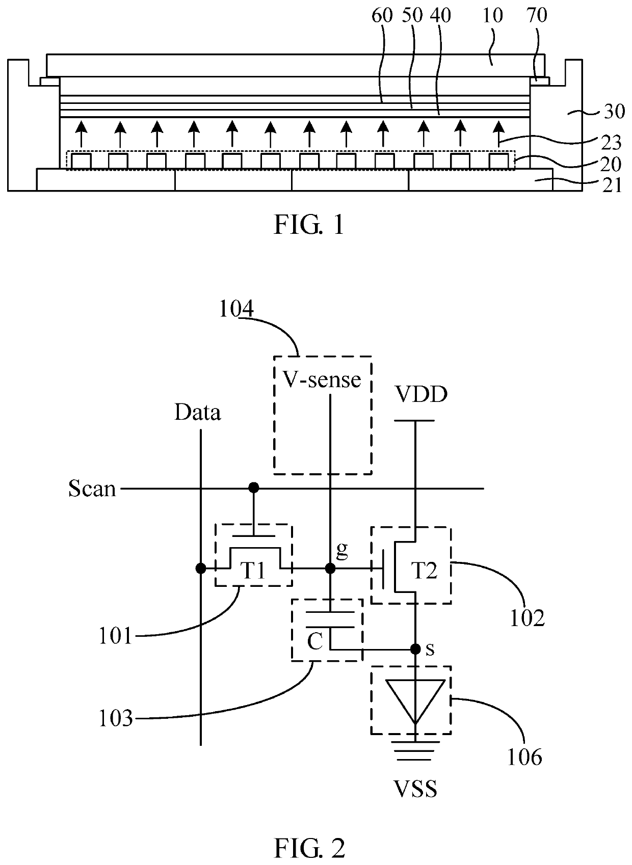
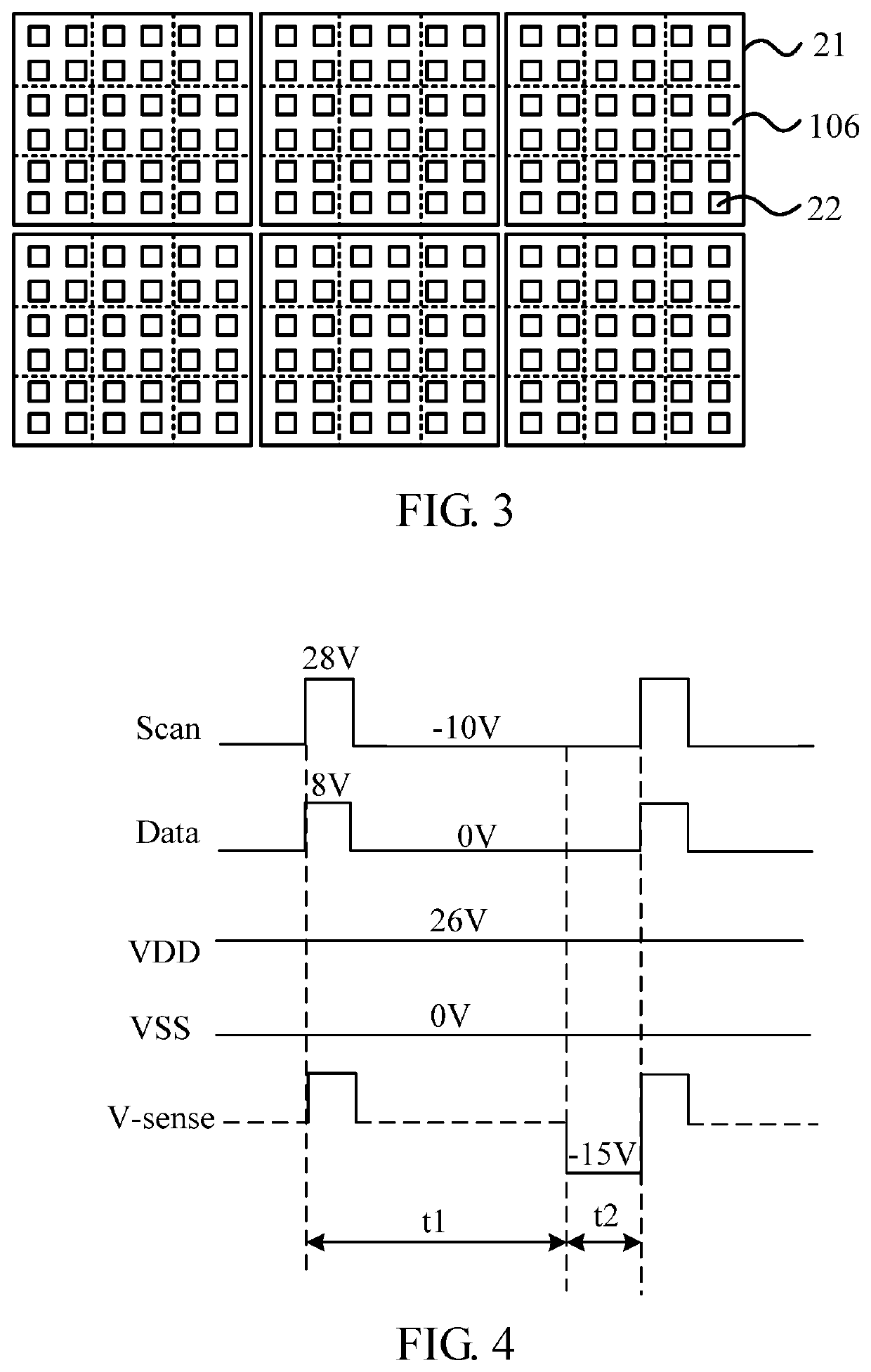
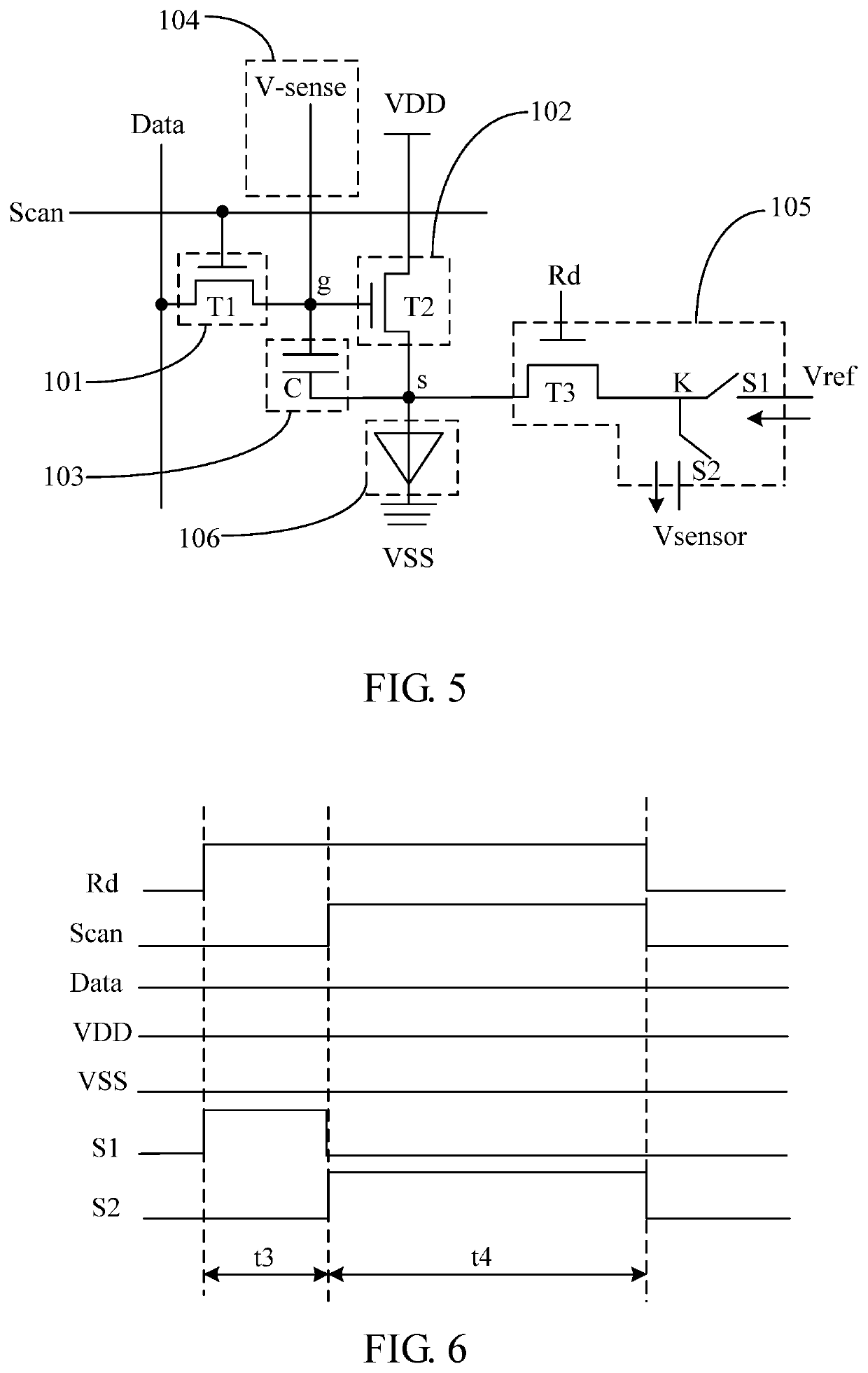
[0042]The following description of each embodiment, with reference to the accompanying drawings, is used to exemplify specific embodiments which may be carried out in the present invention. Directional terms mentioned in the present invention, such as “top”, “bottom”, “front”, “back”, “left”, “right”, “inside”, “outside”, “side”, etc., are only used with reference to the orientation of the accompanying drawings. Therefore, the used directional terms are intended to illustrate, but not to limit, the present invention. In the drawings, components having similar structures are denoted by the same numerals.

[0043]An embodiment of the present application provides a display device, and the display device can be a mobile phone, a computer, a tablet, an electronic watch, or the like. As shown in FIG. 1, the display device includes a backlight module and a liquid crystal display panel 10. The liquid crystal display panel 10 is fixed on a plastic frame 30 of the backlight module through an adh...


PUM


Abstract

A backlight module and a display device are provided. The backlight module includes a backlight source and a driving circuit for driving the backlight source. In the driving circuit corresponding to at least one backlight unit of the backlight source, a driving module is connected to a data signal input module and a compensation module through a first node, and is connected to the backlight unit through a second node. The compensation module is configured to pull down a potential of the first node to be less than a potential of the second node during a blank frame phase to make the threshold voltage of the driving module negatively biased.

Description

FIELD OF INVENTION[0001]The present application relates to the field of display technologies, in particular to a backlight module and a display device.BACKGROUND OF INVENTION[0002]At present, backlight modules using mini light-emitting diodes (mini-LEDs) or micro light-emitting diodes (micro-LEDs) as a backlight source can greatly improve display effect of liquid crystal display panels. Therefore, mini-LEDs and micro-LEDs are important fields for the future development of displays. Conventional LEDs often use a driving circuit to emit light, but when the LEDs emit light for a long time, a threshold voltage of a driving transistor in the driving circuit is prone to forward bias, resulting in an insufficient charging of the LEDs, and brightness will decrease after a long light emission time, which will affect the display effect.[0003]Therefore, the conventional LED backlight modules have a technical problem that brightness of the LEDs decreases after a long light emission time, and ne...

Claims


Application Information

Patent Timeline
IPC IPC(8): G09G3/34G09G3/36
CPCG09G3/3426G09G3/36G09G2320/0233G09G2300/0842G09G2310/08G09G2310/061G09G3/3413G09G2320/0626G09G3/32G09G2300/0819G09G2310/0251G09G2320/0295G09G2320/0693
Inventor LIU, XINGYI
Owner SHENZHEN CHINA STAR OPTOELECTRONICS SEMICON DISPLAY TECH CO LTD
Why Eureka
Try Eureka