

Photoelectric conversion device for solar photovoltaic generation
a conversion device and photovoltaic technology, applied in the field of photoelectric conversion devices, can solve the problems of large device size, increased cost, and possible energy loss, and achieve the effects of preventing light emission from the portion, and reducing the amount of fluorescent substances
- Summary
- Abstract
- Description
- Claims
- Application Information
AI Technical Summary
Benefits of technology
Problems solved by technology
Method used
Image

Examples
Embodiment Construction
Basic Configuration of Photoelectric Conversion Device
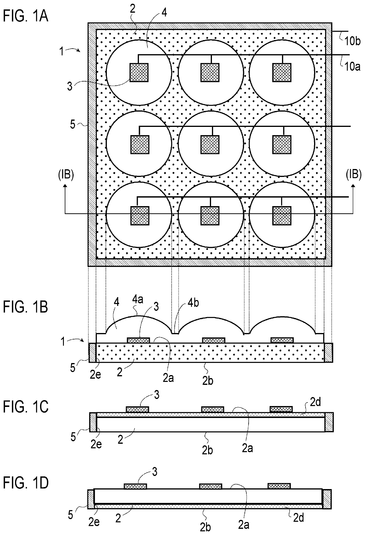
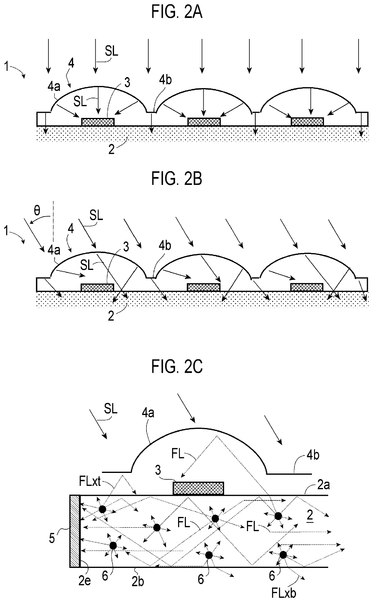
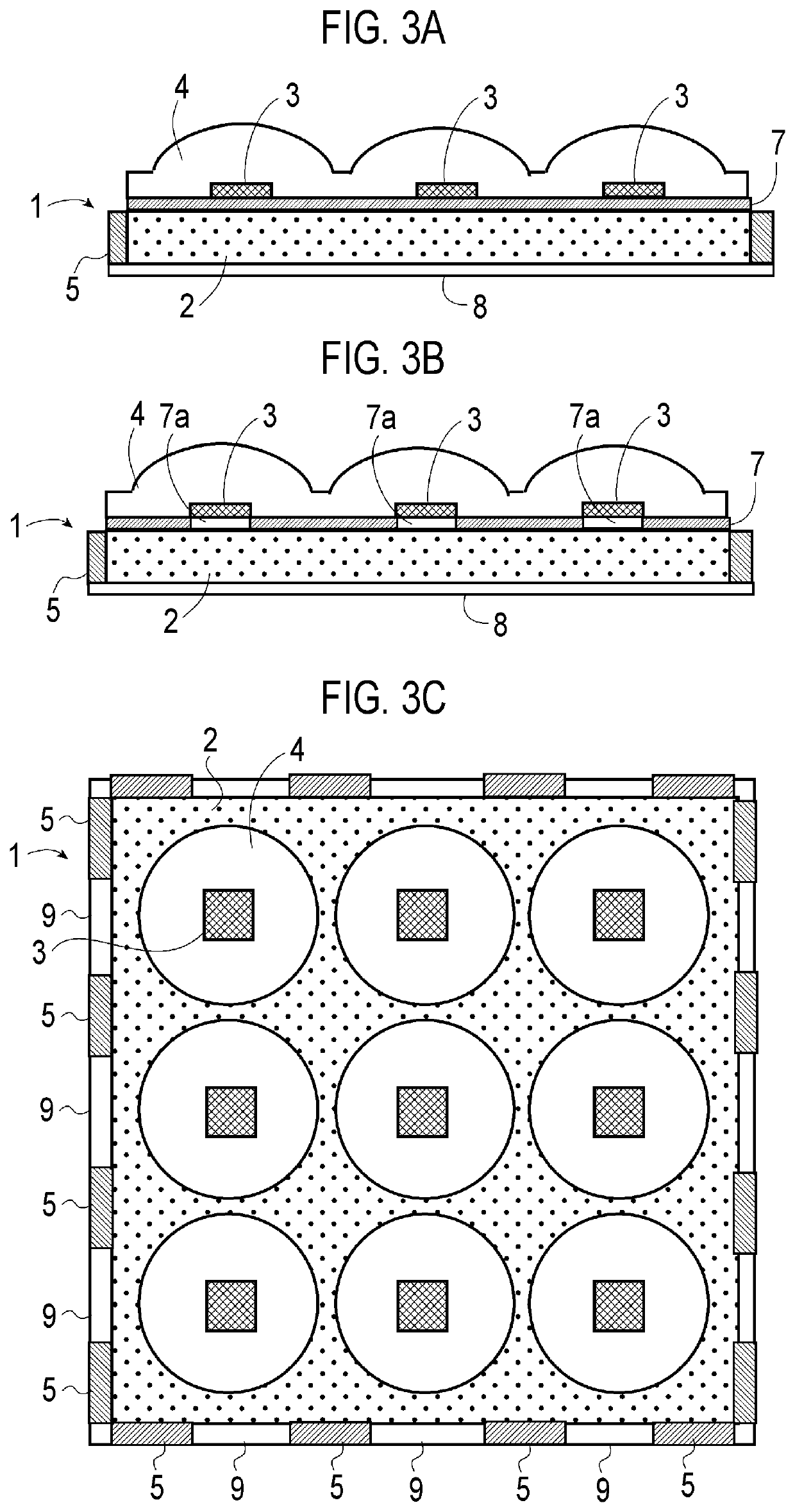
[0032]With reference to FIGS. 1A and 1B, the basic configuration of a photoelectric conversion device 1 of the present embodiment includes a fluorescent light guide plate 2 having a plate-shaped structure, photoelectric cells (first photoelectric cells) 3 mounted on a first surface (upper surface in drawings) 2a of the fluorescent light guide plate 2, a lens layer 4 overlapping the upper surface 2a of the fluorescent light guide plate 2 and the photoelectric cells 3, and a photoelectric cell (second photoelectric cell) 5 disposed on edge surfaces 2e of the fluorescent light guide plate 2. As shown in the drawings, power generated by the photoelectric cells 3 and 5 may be extracted through power lines 10a and 10b.
[0033]In the above-described photoelectric conversion device 1, as shown in the drawings, the fluorescent light guide plate 2 is used as a substrate on which the photoelectric cells 3 that absorb sunlight to generate pow...
PUM
| Property | Measurement | Unit |
|---|---|---|
| thickness | aaaaa | aaaaa |
| angle | aaaaa | aaaaa |
| angle | aaaaa | aaaaa |
Abstract
Description
Claims
Application Information