Headlight controller and vehicle headlight system

a headlight controller and headlight technology, applied in the direction of fixed installation, transportation and packaging, light and heating equipment, etc., can solve the problems of subject visibility degradation in the forward direction, and achieve the effect of simple structure, easy driving, and high reliability

Active Publication Date: 2017-09-05
STANLEY ELECTRIC CO LTD
View PDF12 Cites 2 Cited by
  • Summary
  • Abstract
  • Description
  • Claims
  • Application Information

AI Technical Summary

Benefits of technology

[0022]The presently disclosed subject matter has been devised in view of the above and other characteristics, desires, and problems in the conventional art. An aspect of the disclosed subject matter can include headlight controllers including an ADB for controlling a right and left headlight, which can input light-emitting control signal from the headlight controllers so as to provide favorable light distribution patterns to safely drive at night, and which can prevent a light-emission of glare type light to oncoming vehicles and vehicles moving forward on a driving lane of a subject vehicle incorporating the headlight controller under the various traffic conditions. Another aspect of the disclosed subject matter can include providing vehicle headlight systems including the headlight controller and a right and left optical unit, which can be used as the right and left headlight having a high reliability for the headlight controller, and which can be easy to reduce a size of the headlight with a simple structure. The vehicle headlight systems can provide a favorable light distribution pattern that can be easy to drive at night for not only the subject vehicle but also vehicles traveling in a frontward direction of the subject vehicle by utilizing the characteristics of the headlight controller and the optical unit.
[0027]According to the aspects of the disclosed subject matter, when the camera detects a forward vehicle in a forward direction of the subject vehicle incorporating the headlight controller while driving the subject vehicle projecting a light distribution pattern, the headlight controller can enable the light-emitting area controller to output the light-emitting area data in accordance with the vehicle data output from the vehicle detector to the light distribution controller, and also can enable the light distribution controller to output the light-emitting control signal generated by referring a light-emitting pattern table having applicable relative light intensities of the light-emitting pattern to the right and left headlight. Therefore, the headlight controller can provide a favorable light distribution pattern to safely drive at night while preventing the right and left headlight from emitting a glare type light to oncoming vehicles and vehicles moving forwards in the forward direction of the subject vehicle in accordance with various traffic conditions.
[0028]Furthermore, the optical unit of the headlight system can be used as the right and left headlight having a high reliability with a simple structure. Thus, the disclosed subject matter can also provide vehicle headlight systems using the headlight controller and the optical units, which can provide a favorable light distribution pattern that can be easy to drive at night for the subject vehicle and other vehicles traveling near the subject vehicle by utilizing the characteristics of the headlight controller and the optical unit.

Problems solved by technology

Accordingly, such the lighting control may cause a degradation of visibility in a forward direction of the subject vehicles using the conventional headlight system 50.

Method used


Image

  • Headlight controller and vehicle headlight system
  • Headlight controller and vehicle headlight system
  • Headlight controller and vehicle headlight system

Examples


Embodiment Construction

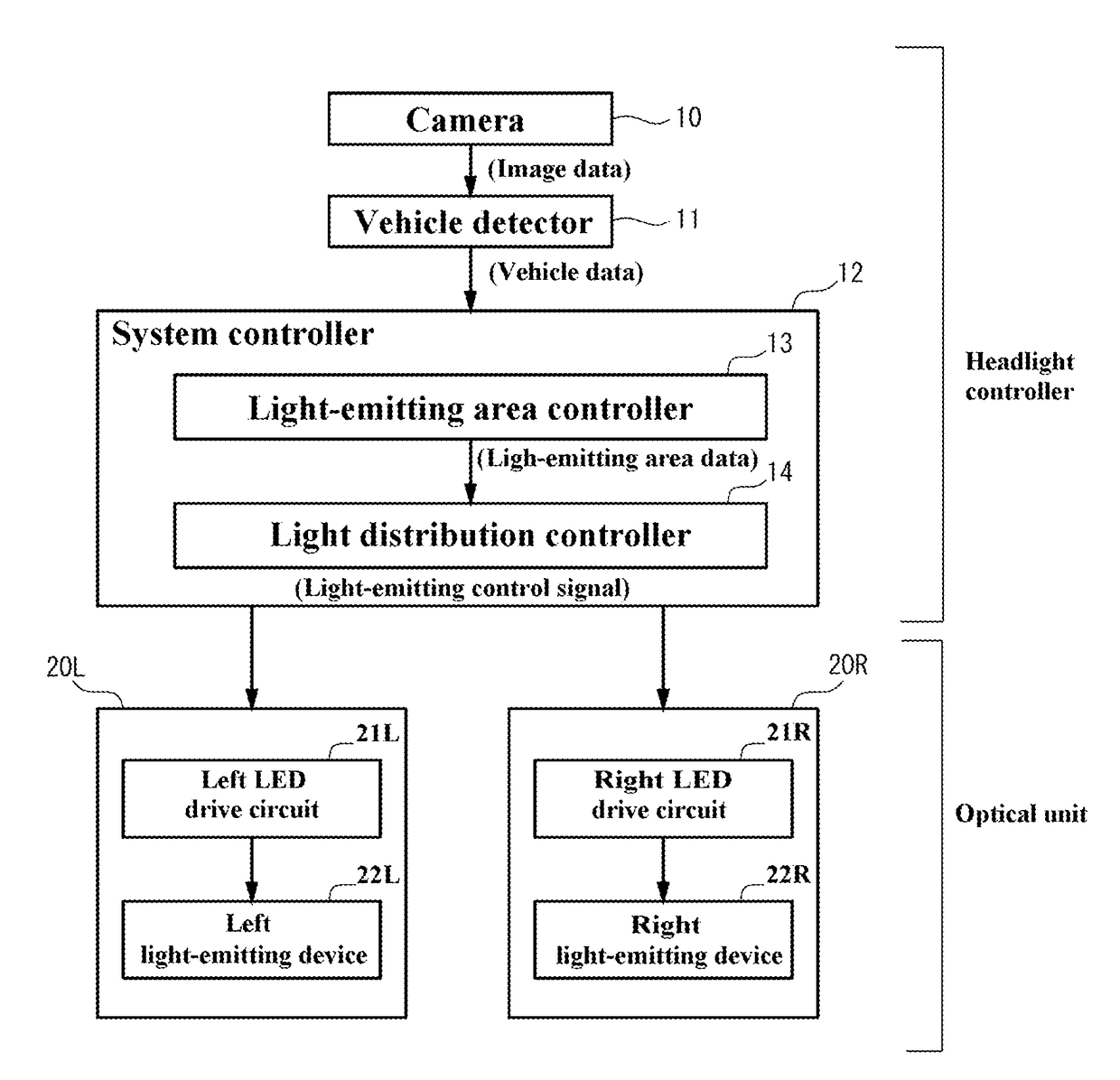
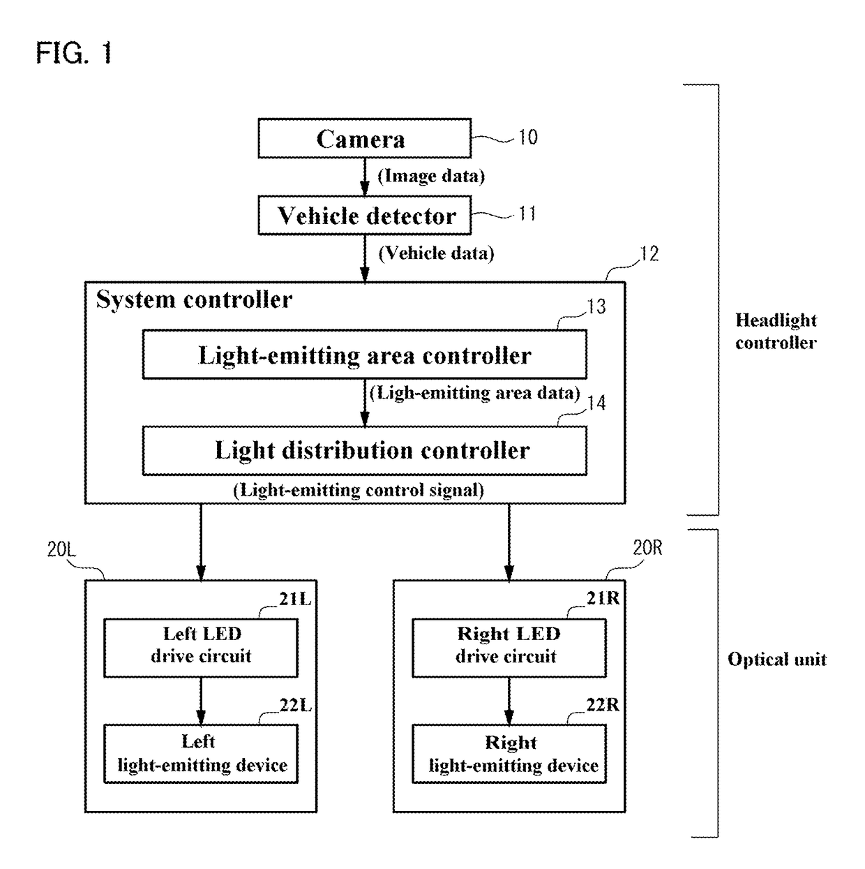
[0037]The disclosed subject matter will now be described in detail with reference to FIG. 1 to FIG. 6. FIG. 1 is a block diagram showing an exemplary embodiment of a vehicle headlight system including a headlight controller and a right and left optical unit made in accordance with principles of the disclosed subject matter. The vehicle headlight system can include the headlight controller and the right and left optical unit 20R and 20L, which can be used as a right and left headlight for a subject vehicle incorporating the headlight controller therein.

[0038]The headlight controller can include: a camera 10 having an optical axis CA (as described with reference to FIG. 4a later) located at a predetermined position in a forward direction of the subject vehicle (e.g., close to a vehicle interior mirror), photographing an objective space in the forward direction of the subject vehicle, configured to photograph at least one vehicle (at least one oncoming vehicle and at least one forward ...


PUM


Abstract

A headlight controller and a vehicle headlight system including an ADB can include a headlight controller and an optical unit. The headlight controller can include a system controller, a vehicle detector and a camera photographing forward vehicles located in a travelling direction of a subject vehicle, and the system controller can be configured to output a light-emitting control signal to provide favorable light distribution patterns by using vehicle data output from the vehicle detector in accordance with image data output from the camera. The optical unit can be configured to provide the favorable light distribution patterns using lights emitted from a right and left light-emitting device in accordance with the light-emitting control signal. Thus, the disclosed subject matter can include providing vehicle headlight systems that can form various favorable light distribution patterns by utilizing the characteristics of the headlight controller and the optical unit in accordance with various traffic conditions.

Description

[0001]This application claims the priority benefit under 35 U.S.C. §119 of Japanese Patent Application No. 2015-099427 filed on May 14, 2015, which is hereby incorporated in its entirety by reference.BACKGROUND[0002]1. Field[0003]The presently disclosed subject matter relates to headlight controllers and vehicle headlight systems, and more particularly to vehicle headlight systems including an adaptive driving beam (ADB) using an optical unit, and the vehicle headlight systems having favorable light distribution patterns, which can be easy to drive at night, and which can prevent the optical unit from emitting a glare type light to oncoming vehicles on an oncoming traffic lane and vehicles moving forward on a driving lane.[0004]2. Description of the Related Art[0005]When drivers steer a car at night, the drivers usually want to steer the car while they turn on headlights for a high beam to improve a visibility. However, drivers must drive the car while they switch between the headli...

Claims


Application Information

Patent Timeline
Patent Type & Authority Patents(United States)
IPC IPC(8): B60Q1/14F21S8/10
CPCB60Q1/1423F21S48/1154F21S48/1747B60Q2300/056B60Q2300/41B60Q2300/42F21S48/125B60Q1/143F21S41/153F21S41/25F21S41/663
Inventor NAKATANI, AKIHIRO
Owner STANLEY ELECTRIC CO LTD
Why Eureka
Try Eureka