Light guide for a lighting device

a technology for lighting devices and light guides, applied in the direction of optical light guides, instruments, optics, etc., to achieve the effect of preventing light emission of higher intensity

Active Publication Date: 2018-01-25
HELLA KG HUECK & CO
View PDF19 Cites 0 Cited by
  • Summary
  • Abstract
  • Description
  • Claims
  • Application Information

AI Technical Summary

Benefits of technology

[0006]It is therefore an object of the invention to provide a light guide with an improved cover on one end face of the light guide, in order to prevent light emission of higher intensity in the end region.

Problems solved by technology

However, such a cover requires a further part, for example, as a component of the light guide receiver, which is not generally available as a function of the installation position of a light guide.

Method used


Image

  • Light guide for a lighting device
  • Light guide for a lighting device

Examples


Embodiment Construction

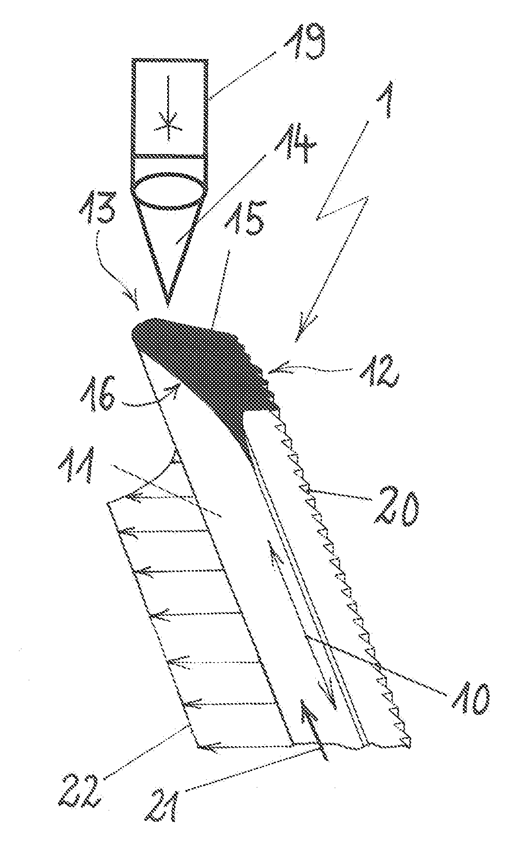
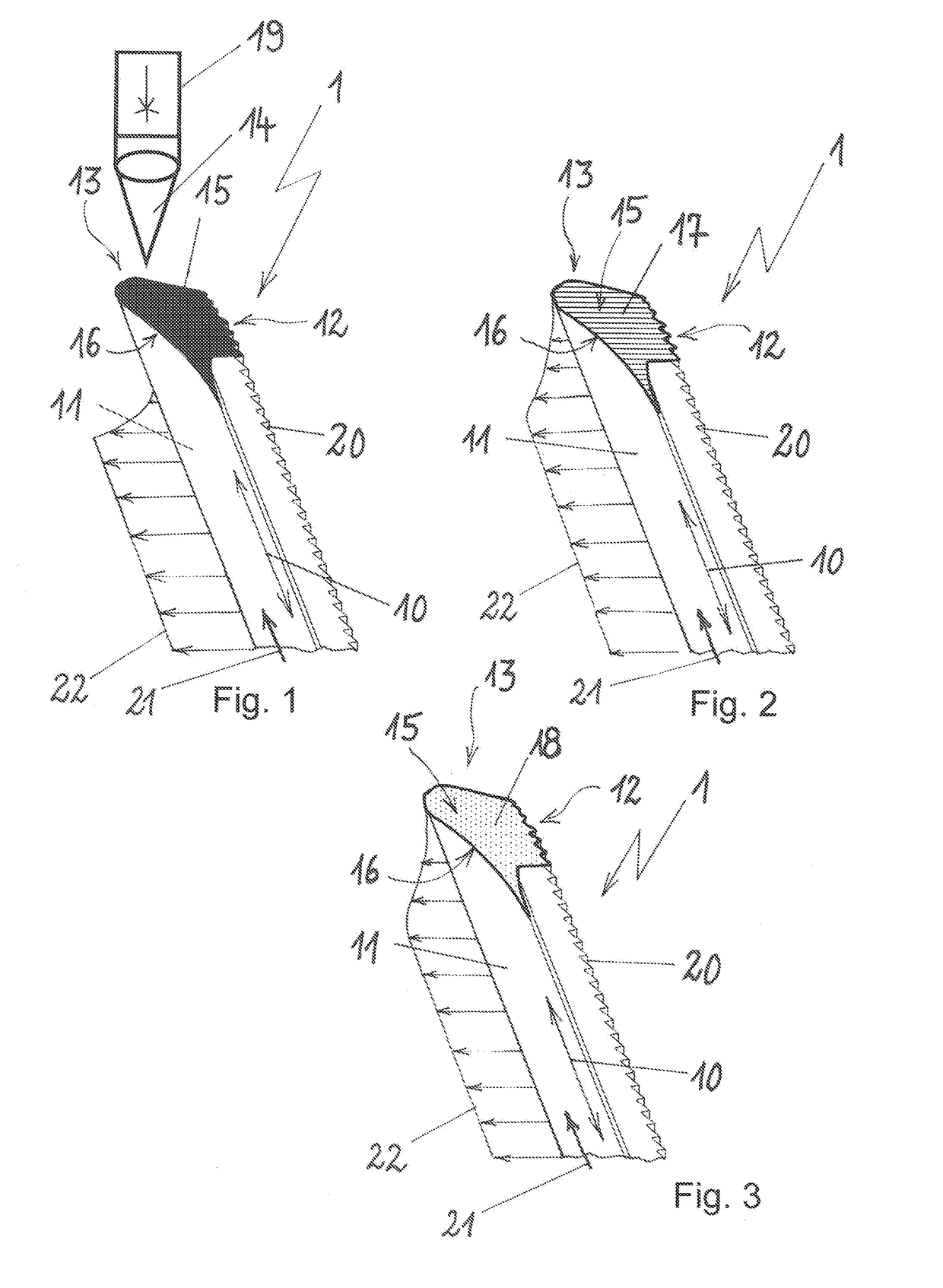
[0021]FIGS. 1, 2 and 3 respectively show a light guide 1 with a different embodiment of a cover 13 formed according to the invention in the end region 12 of the light guide 1. The light guide 1 extends along a longitudinal axis 10 and over the longitudinal axis 10, the light guide 1 has a coupling-out area 11 via which light 21 is coupled out having a substantially constant intensity. By way of example, an intensity profile 22 is shown which substantially has an equal intensity over the longitudinal extension of the light guide 1 along the longitudinal axis 10. In the end region 13 of the light guide 1, an end face 16 closes off the light guide 1 so that the intensity of the intensity profile 22 changes along the longitudinal axis 10 when it reaches the end face 16.

[0022]For coupling out the coupled-in light 21 via the coupling-out area 11 there is a prism structure 20 which is provided opposite the coupling-out area 11. According to the principle of total reflection, the light 21 i...


PUM


Abstract

A light guide for a lighting device, wherein the light guide extends along a longitudinal axis and has a coupling-out area which runs over the longitudinal axis and from which light can be emitted along the longitudinal axis, and wherein the light guide has, in its longitudinal extent, an end region which is provided with a cover in order to suppress high-intensity light emission in the end region. The cover is formed by laser-machining the light guide material in the end region of the light guide. The invention further relates to a method for forming a cover in the end region of the light guide.

Description

[0001]This nonprovisional application is a continuation of International Application No. PCT / EP2016 / 056919, which was filed on Mar. 30, 2016, and which claims priority to German Patent Application No. 10 2015 105 168.0, which was filed in Germany on Apr. 2, 2015, and which are both herein incorporated by reference.BACKGROUND OF THE INVENTIONField of the Invention[0002]The present invention relates to a light guide for a lighting device, wherein the light guide extends along a longitudinal axis and has a coupling-out area extending about the longitudinal axis from which light can be emitted along the longitudinal axis, and wherein the light guide in its longitudinal extension has an end region, which is provided with a cover in order to prevent light emission of higher intensity.Description of the Background Art[0003]Light guides are used for the transmission of light coupled into the light guide, and light guides are known, which have over their longitudinal extension a prismatic st...

Claims


Application Information

Patent Timeline
Patent Type & Authority Applications(United States)
IPC IPC(8): F21V8/00
CPCG02B6/0065G02B6/0043G02B6/0061
Inventor DIRKS, HEINZ-MICHAELSCHOENING, FRANKSTUHLDREHER, MARKUSSURAY, ANDREASWILLEKE, FRANZ-GEORG
Owner HELLA KG HUECK & CO
Why Eureka
Try Eureka