Removing Device for Dentistry

Pending Publication Date: 2022-06-16
SHIH JUI YUAN
View PDF0 Cites 0 Cited by
  • Summary
  • Abstract
  • Description
  • Claims
  • Application Information

AI Technical Summary

Benefits of technology

The present invention provides a convenient and effective removing device for dentistry that can be quickly and easily used during bone grafting procedures. The device uses a hard water suction / high power suction through a simplified structural configuration to remove bone grafts that may enter the sinus cavity, which can prevent infection and suppuration. The device is easy to use and can be quickly removed, providing a solution to potential surgeries or life-threatening conditions. It is manufactured and produced conveniently, allowing dentists to operate easily and quickly to start the procedure. Overall, the technical effects of the invention include providing a reliable, safe, and convenient tool for dental procedures.

Problems solved by technology

However, the conventional water suction / high power suction is mainly a hard structure made of materials such as plastic or metal.
During the operation, it may cause a collision that hurts the patient, and the materials of the hard structure cannot be adjusted as needed, which relatively restricts the practicability of the conventional water suction / high power suction.
Since there is no related technology to remove the bone graft that has fallen into the sinus cavity, it can only be expected that the bone graft may be discharged into the nasal cavity through the sinus opening of the maxillary sinus that communicates with the sinus cavity.
When the bone graft in the sinus cavity cannot be discharged smoothly through the sinus opening of the maxillary sinus, it will cause the bone graft to block the sinus opening of the maxillary sinus, and infection and suppuration inside the sinus cavity will cause the sinus of the maxillary sinus infection.
In severe cases, the bacteria will spread into the brain, causing damage to the brain that can be life-threatening.
At this time, the patient can only be transferred to an otolaryngologist through functional endoscopic sinus surgery (FESS), which is quite risky for patients and is likely to cause medical disputes.

Method used


Image

  • Removing Device for Dentistry
  • Removing Device for Dentistry
  • Removing Device for Dentistry

Examples


first embodiment

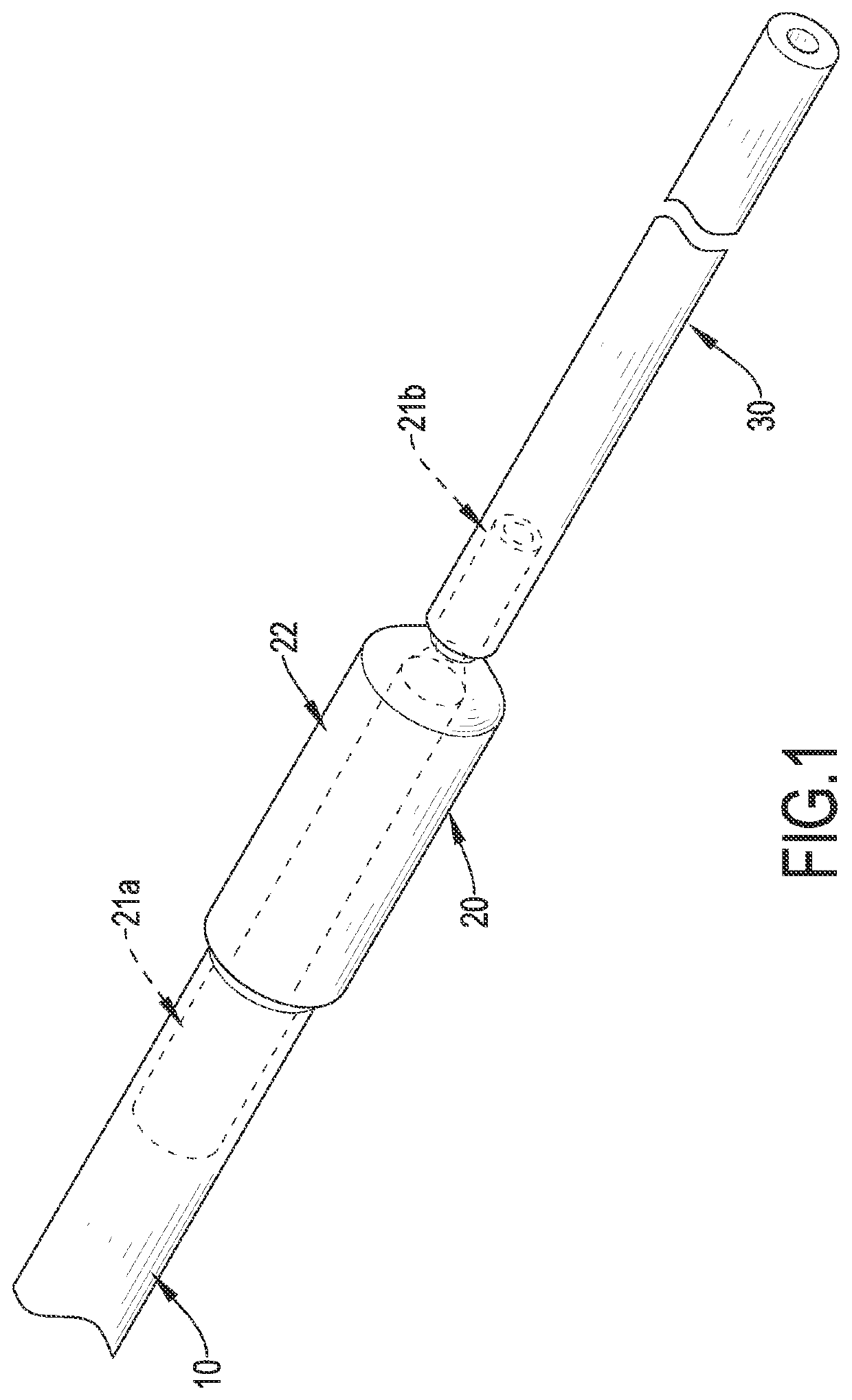
[0035]The present invention is a removing device for dentistry; with reference to FIG. 1, a removing device for dentistry in accordance with the present invention comprises a connecting pipe 10, a controller 20, and a sucking tube 30. Each of the connecting pipe 10 and the sucking tube 30 is made of a soft material, and an end of the connecting pipe 10 is connected to a hard water suction / high power suction 50 as shown in FIG. 3. The controller 20 is a hollow jacket and has two connecting portions 21a, 21b and an operating portion 22 disposed between the two connecting portions 21a, 21b. Furthermore, the two connecting portions 21a, 21b are respectively a first connecting portion 21a and a second connecting portion 21b, and the two connecting portions 21a, 21b are in fluid communication with each other via the operating portion 22. The first connecting portion 21a is connected to the connecting pipe 10, and the second connecting portion 21b is distal from the connecting pipe 10 and ...

third embodiment

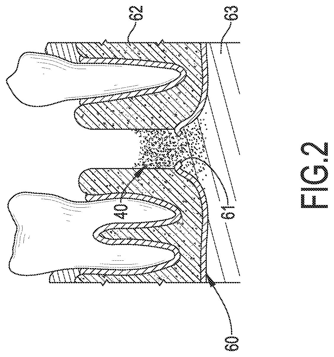
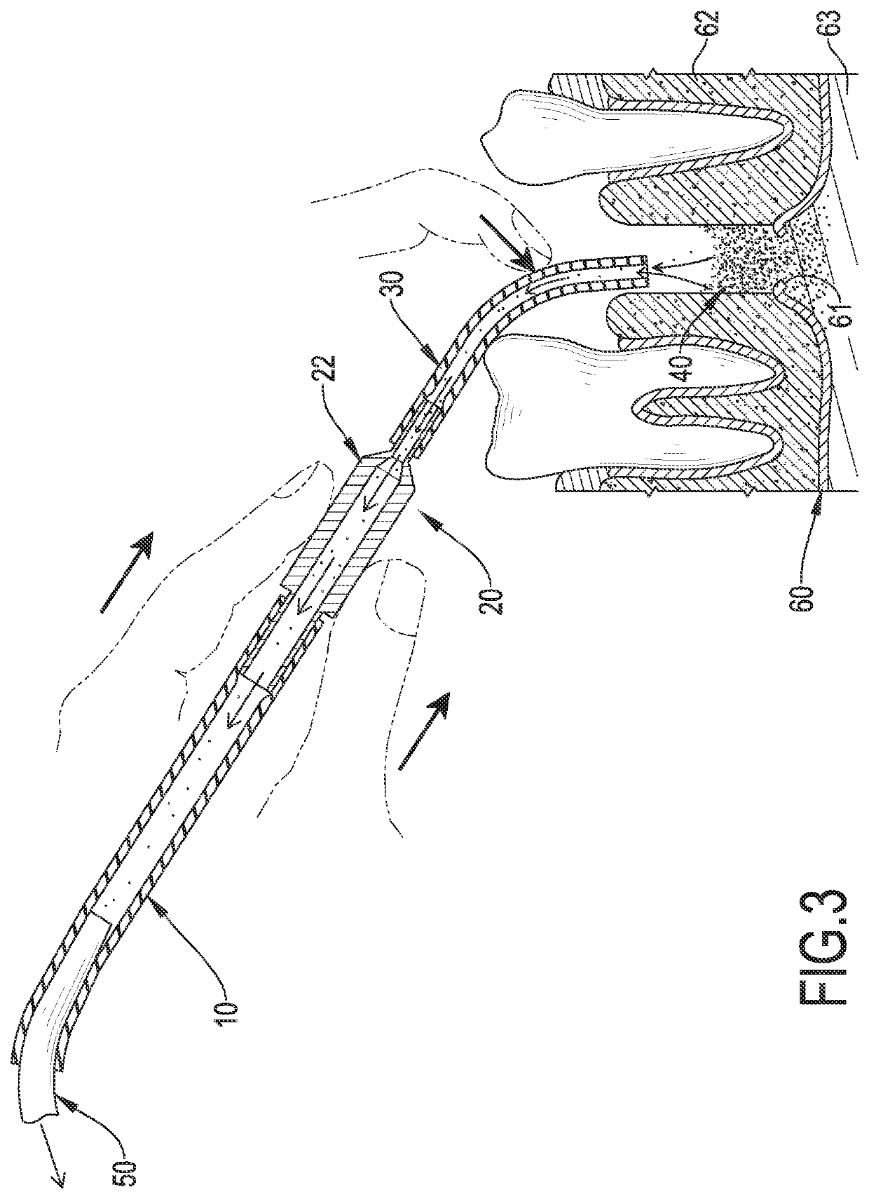
[0039]With reference to FIGS. 8 and 9, when the removing device for dentistry of the present invention is in use, the connecting pipe 10 is connected to the water suction / high power suction 50 by the dentist, and the dentist can hold the controller 20 by one hand to move the sucking tube 30 at the patient's alveolar bone 62 or the other hand assists in moving the sucking tube 30 at the alveolar bone 62. With reference to FIG. 8, the dentist covers the relief hole 221 by fingers, so that the gas suction in the water suction / high power suction 50 can be transmitted to the sucking tube 30, and the bone graft 40 that enters the sinus cavity 63 can be sucked out through the sucking tube 30 to prevent the bone graft 40 from blocking the sinus opening of the maxillary sinus to generate infection and suppuration in the sinus cavity 63. Furthermore, during the operation of removing the bone graft 40, the dentist can separate the finger from or approach the relief hole 221 as shown in FIG. 9 ...

seventh embodiment

[0044]With reference to FIG. 17, when the removing device for dentistry of the present invention is in use, when the sucking tube 30 is moved deep into the patient's oral cavity to remove the bone graft 40, the predetermined drilling depth during dental implantation can be matched with a corresponding length of the sucking tube 30, and the length of the sucking tube 30 can be cut according to the reverse mark 312, so that when the dentist moves the sucking tube 30 into the alveolar bone 62 of the patient, the free end of the sucking tube 30 will not extend too much into the sinus cavity 63, but will be located at the hole 61 for removing the bone graft 40 that drops into the sinus cavity 63. While the sucking tube 30 is inserted, the prompt symbol 313 on the side of the reverse mark 312 can be used to remind the dentist that the free end of the sucking tube 30 is located in the hole 61. Therefore, the dentist can accurately remove the bone graft 40 located at the hole 61, and can pr...


PUM


Abstract

A removing device for dentistry has a connecting pipe, a controller, and a sucking tube. The controller is connected to the connecting pipe and has two connecting portions and an operating portion between the two connecting portions. The two connecting portions connect in fluid communication with each other via the operating portion. One of the connecting portions is connected to the connecting pipe. The operating portion has at least one relief hole disposed on an external surface thereof and in fluid communication with the connecting portions and a flow regulator. The sucking tube is connected to the other connecting portion opposite to the connecting pipe to connect in fluid communication with the connecting pipe via the controller. By pressing the operating portion to shield the relief hole or adjust the flow regulator to control the suction force, the removing device for dentistry can be used conveniently and removed quickly.

Description

BACKGROUND OF THE INVENTION1. Field of the Invention[0001]The present invention relates to a removing device for dentistry, and more particularly to a removing device for dentistry that can be used and manufactured conveniently and can be removed quickly.2. Description of Related Art[0002]With the advancement and development of science and technology, the current technology and equipment related to dental health and treatment are also flourishing. In a process of dental health care and treatment, it is often necessary to use a conventional water suction / high power suction to draw out the patient's saliva and rinsing fluid to avoid leaving the saliva or rinsing fluid in the patient's mouth that may affect subsequent related operations. However, the conventional water suction / high power suction is mainly a hard structure made of materials such as plastic or metal. During the operation, it may cause a collision that hurts the patient, and the materials of the hard structure cannot be a...

Claims


Application Information

Patent Timeline
IPC IPC(8): A61C17/12A61C17/08
CPCA61C17/13A61C17/08A61C19/04
Inventor SHIH, JUI YUAN
Owner SHIH JUI YUAN
Why Eureka
Try Eureka