Dual flush device for toilet water tank

Inactive Publication Date: 2011-04-28
LI CHUNG HSIEN
View PDF43 Cites 9 Cited by
  • Summary
  • Abstract
  • Description
  • Claims
  • Application Information

AI Technical Summary

Benefits of technology

[0008]The present invention achieves the intention of controlling the quantity of water-release in the best way by using a simple mechanism of dual flush. It is not only quick and easy installation but also adapt

Problems solved by technology

But this mechanism makes the water drains out totally.
The quantity of water can not be controlled a

Method used


Image

  • Dual flush device for toilet water tank
  • Dual flush device for toilet water tank
  • Dual flush device for toilet water tank

Examples


first embodiment

The First Embodiment

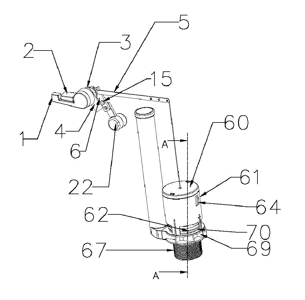
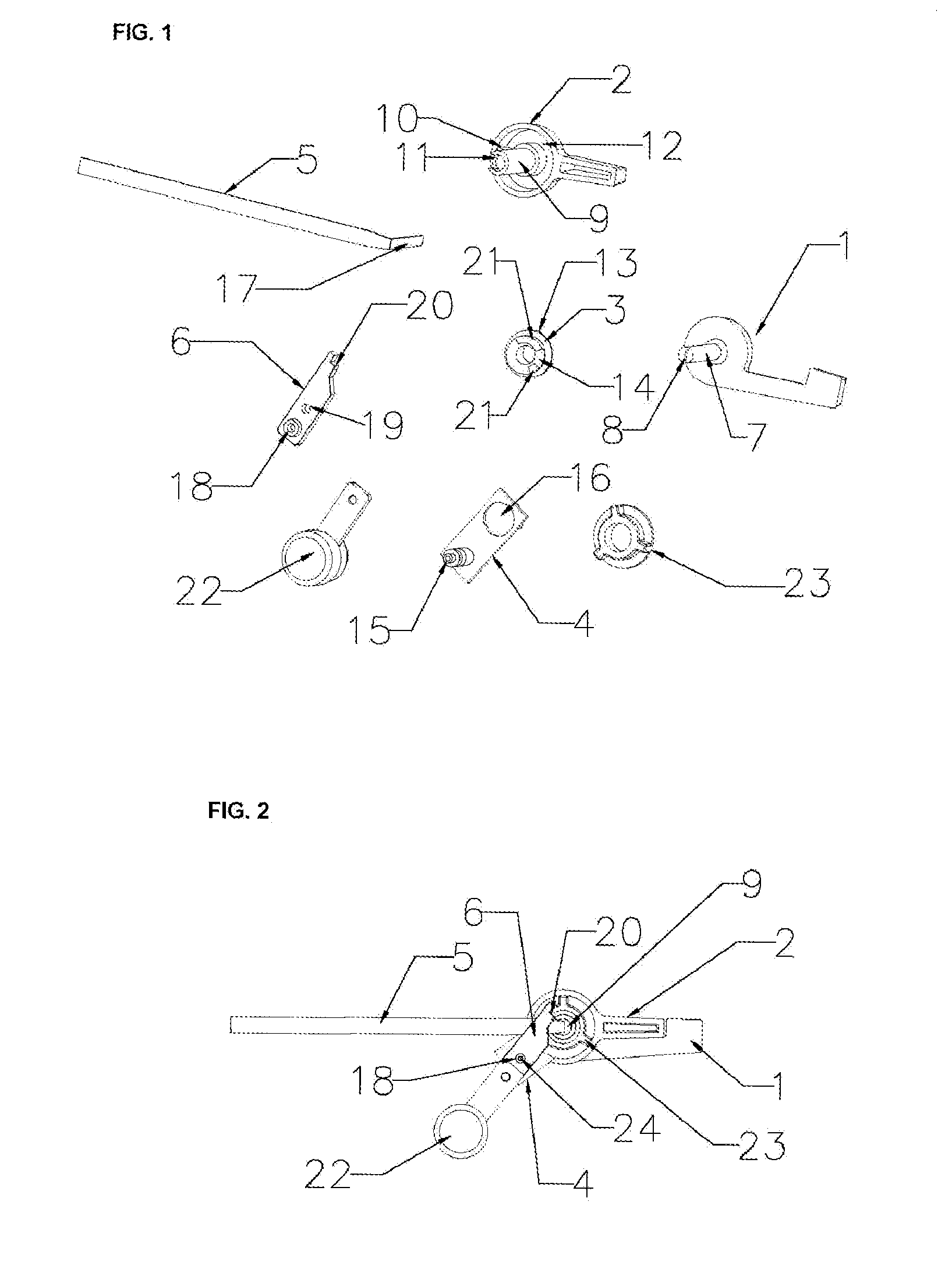
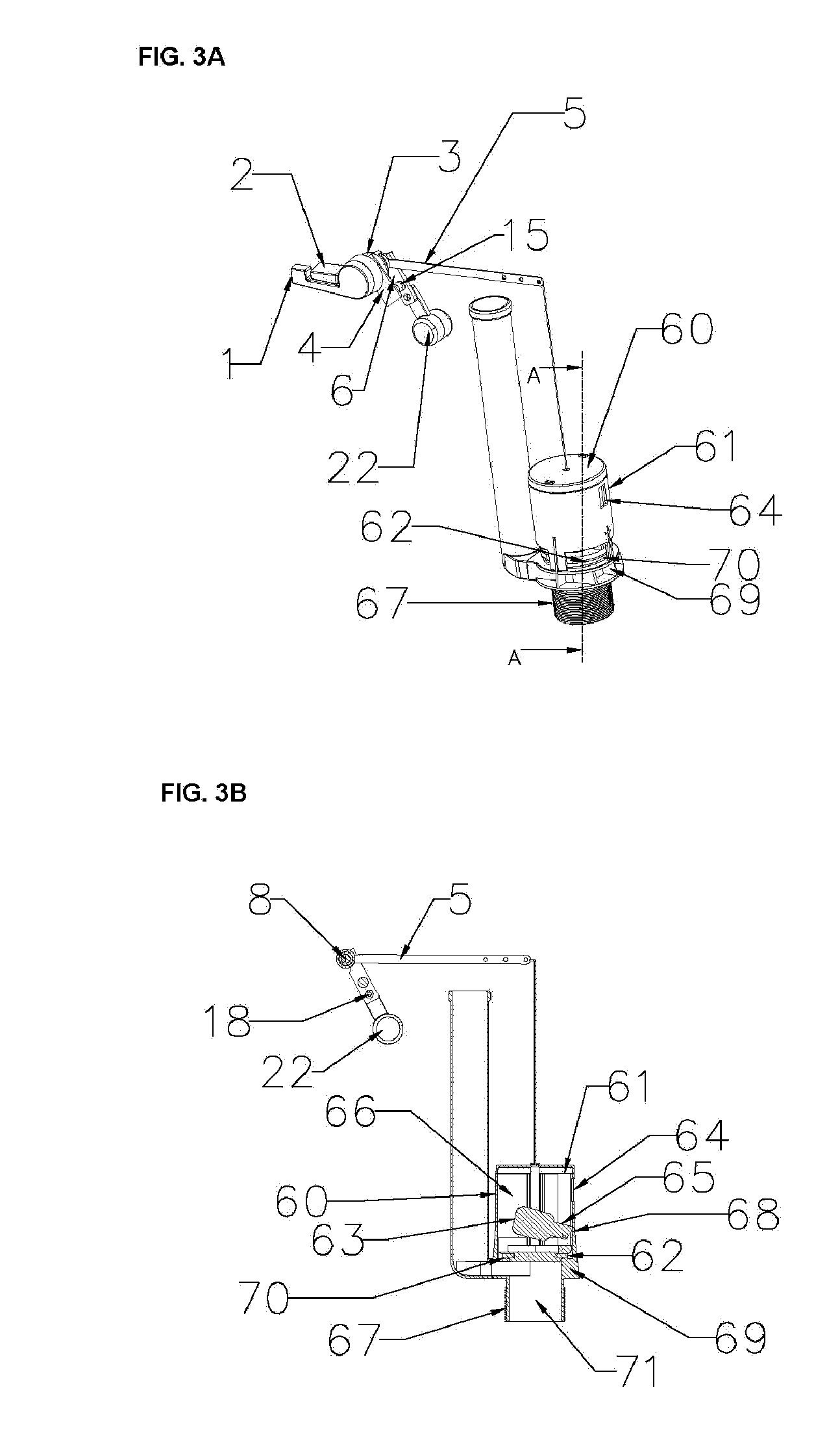
[0022]Referring now to FIG. 3A, there is illustrated a dual flush device for a toilet water tank according to the present invention. At one side wall of a water tank there is provided a manually-operated press handle, (FIGS. 1, 2 and FIG. 11). The press handle comprises a first switch-bar (2) and a second switch-bar (1). A dent or depressed surface (12) sits inside the first switch-bar (2), and a pivot (9) is at the center of the dent (12). Within the pivot (9) there is a hollow roundness with a notch (11) at upper side. A retaining blockade (10) is set inside the dent (12) and connected with the pivot (9). A axial stick or axle (7) which has a axial hole (8) inside, is installed at the central part of one end of second switch-bar (1). When the axial stick (7) is put into the hollow roundness of the pivot (9), the first switch-bar (2) is mounted on the second switch-bar (1).

[0023]On the first switch-bar (2), there is a hollow bed (3) comprising a protruding tube ...

second embodiment

The Second Embodiment

[0027]Moreover, now referring to FIGS. 5, 9, and 10, there is provided a dual flush device for a toilet water tank. In this dual flush device, there is installed a manually-operated press button switch (31) (FIG. 4) at the lid of the water tank. The device comprises a water-drainer (60) as described in the first embodiment. The press button switch (31) includes a first depressor (33) and a second depressor (34). Under the first depressor (33) there is located a retaining blockade (35), but there is no retaining blockade located under the second depressor (34). The first depressor (33) and the second depressor (34) are fixed in the inner space of a box (38). A movable driving-rod (36) is set under them. In the middle of box (38) there is provided a round hole to allow the driving-rod (36) move forward and backward.

[0028]On a mandrel (53) of the driving-rod (36) there is set a coil spring (52) (FIG. 4). A fixation bed (50) has a hollow outer screw thread (51). The...


PUM


Abstract

The present invention is related to a dual flush device for toilet water tank. A manually-operated press handle, in which a first switch-bar and a second switch-bar are intercalated on, is installed on a side-wall of the water tank. The switch-bar has a hollow bed, the tube of the hollow bed has a pivotal hole of the holder. The front edge of a bent-arm conjugates with an axial hole of the second switch-bar, the other end of the bent-arm has a chain which is fixed in a central hole of a moving element of a water-drainer. The round axis of the holder conjugates with a conduct hole of a gliding plate; and the screw nut is fixed by a stud to hold a float-ball under water. The water-drainer has a draining part. Inside the draining part there is a moving element. The moving element has a central hole, and a flush valve at the bottom, and a float-ball held in inner space. Below the draining part, there is provided an outer screw-thread, on the outer screw-thread there is mounted a base. In view of the above disclosure, it is the primary intention of the invention to successfully control the quantity of released water by dual flush. This device is not only a simple structure but also easily using at the user's will.

Description

TECHNICAL FIELD OF THE INVENTION[0001]The present invention relates to a dual flush device for a toilet water tank. In particular, the present invention provides an improvement about flush device used in toilet water tank.BACKGROUND ART[0002]There is known that a commercially available flush toilet has a manually operation press handle which is mounted on a sidewall or on the tank lid. When the flush-valve inside the water tank is pulled up by means of pressing down the press handle, the water in the tank is released to the bowl from the drainage hole. But this mechanism makes the water drains out totally. The quantity of water can not be controlled as the user's demand. Furthermore, the prior art known to the inventor is TIPO pat. No. 89200711. The said patent has disclosed a device in which two handles connect to two flap-arms respectively. When the handle is pulled, it comes out a result of controlling one flap-arm or two flap-arms simultaneously operated, and a result of the ope...

Claims


Application Information

Patent Timeline
IPC IPC(8): E03D1/14
CPCE03D5/09E03D1/142
Inventor LI, CHUNG HSIEN
Owner LI CHUNG HSIEN
Why Eureka
Try Eureka