Universal rotary milling and drilling tool with functions of horizontal movement and positioning of hoop

A horizontal movement, milling and drilling technology, applied in the field of milling machines, can solve the problems of complex movement and positioning operations, difficulty in ensuring accurate positions, and low processing and maintenance efficiency, so as to improve construction efficiency and construction accuracy, facilitate fast and accurate movement, Ease of maintenance and replacement

Pending Publication Date: 2019-03-12
罗甸县金泰模具机械制造有限公司
View PDF0 Cites 3 Cited by
  • Summary
  • Abstract
  • Description
  • Claims
  • Application Information

AI Technical Summary

Problems solved by technology

Existing milling machines are mainly of horizontal or vertical structure, which not only has a single function, but also has a large bed volume, and the processing stroke of the milling head is limited, so parts cannot be milled, bored, drilled, etc. It is difficult for a milling machine to process the slope of the workpiece, so for the processing of irregular parts, it often needs to be clamped multiple times or on a variety of machine tools. It can only be completed on a special machine tool, not only the operation is cumbersome, the processing efficiency is low, but the production cost is also high
The existing milling machine is difficult to disassemble and assemble the milling head. During the processing and production process, it is often shut down for maintenance due to the damage of the milling head.
Therefore, the existing milling machines have the disadvantages of large size, single function, cumbersome processing operations, difficult disassembly and assembly of the milling head, and low processing and maintenance efficiency.
[0003] The inventor invented such as: "portable three-axis rotary positioning universal milling machine", "magnetic rear pull rod positioning rotary universal milling machine", "shaft holding positioning rotary universal milling machine" and other small Howeve

Method used


Image

  • Universal rotary milling and drilling tool with functions of horizontal movement and positioning of hoop
  • Universal rotary milling and drilling tool with functions of horizontal movement and positioning of hoop
  • Universal rotary milling and drilling tool with functions of horizontal movement and positioning of hoop

Examples


Embodiment Construction

[0032] The present invention will be further described below in conjunction with the accompanying drawings and embodiments, but not as a basis for limiting the present invention.

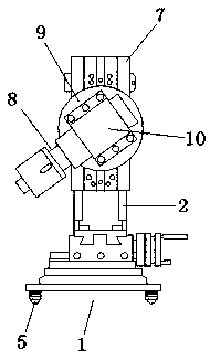
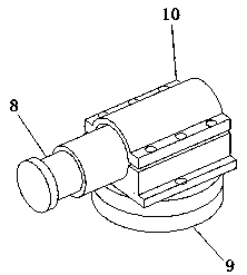
[0033]Example. Horizontal movement positioning hoop universal rotary milling and drilling tools, such as Figure 1 to Figure 12 As shown, it includes a mobile base device 1, a guide rail is provided below the mobile base device 1, and a column 2 is provided above the mobile base device 1. The mobile base device 1 includes a base plate 4, and an electromagnet is provided at the bottom center of the base plate 4. A group of ball screws 5 are provided at the four corners below the base plate 4, and the setting positions of the ball screws 5 are aligned with the guide rails; a positioning installation turntable 6 is provided above the base plate 4, and a rotary knife feed seat is provided above the positioning installation turntable 6; the positioning installation turntable 6 is provided with a bolt gr...


PUM


Abstract

The invention discloses a universal rotary milling and drilling tool with functions of horizontal movement and positioning of a hoop. The universal rotary milling and drilling tool comprises a movingbase device. Guide rails are arranged below the moving base device, and a stand column is arranged on the top of the moving base device. A sliding block is arranged on one side of the stand column, and a milling head rotary positioning device is arranged on the sliding block. The universal rotary milling and drilling tool with the functions of horizontal movement and positioning of the hoop is small in size and convenient to carry, assemble, disassemble, repair and replace. Inclined tool feeding drilling can be conducted in the 360-degree direction, the construction requirement for boring in acircular hole wall or in the inclined direction is met, and the accuracy is high. Meanwhile, rapid and accurate movement is facilitated. In addition, after the universal rotary milling and drilling tool arrives at the construction position, the positioning operation is easy, and the construction efficiency and the construction accuracy can be effectively improved.

Description

technical field [0001] The invention relates to a milling machine, in particular to a universal rotary milling and drilling tool for horizontally moving and positioning hoops. Background technique [0002] Milling machine is an indispensable general-purpose equipment in the machinery manufacturing industry, and it is also a high-yield machine tool in the machine tool industry after the output of lathes. Existing milling machines are mainly of horizontal or vertical structure, which not only has a single function, but also has a large bed volume, and the processing stroke of the milling head is limited, so parts cannot be milled, bored, drilled, etc. It is difficult for a milling machine to process the slope of the workpiece, so for the processing of irregular parts, it often needs to be clamped multiple times or on a variety of machine tools. It can only be completed on a special machine tool, not only the operation is cumbersome, the processing efficiency is low, and the p...

Claims


Application Information

Patent Timeline
IPC IPC(8): B23C1/12B23C1/20B23Q1/26B23Q5/40
CPCB23C1/12B23C1/20B23Q1/26B23Q5/40
Inventor 刘海
Owner 罗甸县金泰模具机械制造有限公司
Why Eureka
Try Eureka