
Automatic leveling device based on joint bearing and application thereof

A technology of joint bearing and leveling device, which is applied to supporting machines, offensive equipment, mechanical equipment, etc., can solve the problems of inconvenient use, time-consuming and laborious, inaccurate, etc., and achieve the effect of reducing installation difficulty, convenient use, and quick installation and operation.

Inactive Publication Date: 2016-01-13
FUJIAN LONGXI BEARING (GROUP) CO LTD
View PDF6 Cites 4 Cited by
  • Summary
  • Abstract
  • Description
  • Claims
  • Application Information

AI Technical Summary

Problems solved by technology

[0002] With the development of technology in the technology industry, many measuring instruments (such as range finders, theodolites, etc.), electronic devices (such as projectors, scanners, etc.), and platforms for installing weapons during shooting training, etc., need to be placed On a horizontal plane, but in many cases the bearing surface of the bearing body carrying these instruments is not flat, or some instruments need to be used frequently in different locations, so the state of the bearing surface of the bearing body is constantly changing, and even some instruments It is necessary to work on a moving carrier. The method of making them level in the prior art is usually to manually adjust them and judge them to be in a horizontal state based on experience. This method is not only inaccurate, but also time-consuming and laborious. Once the carrier is replaced body, it must be readjusted, which is inconvenient to use

Method used


Image

  • Automatic leveling device based on joint bearing and application thereof
  • Automatic leveling device based on joint bearing and application thereof

Examples


Embodiment Construction

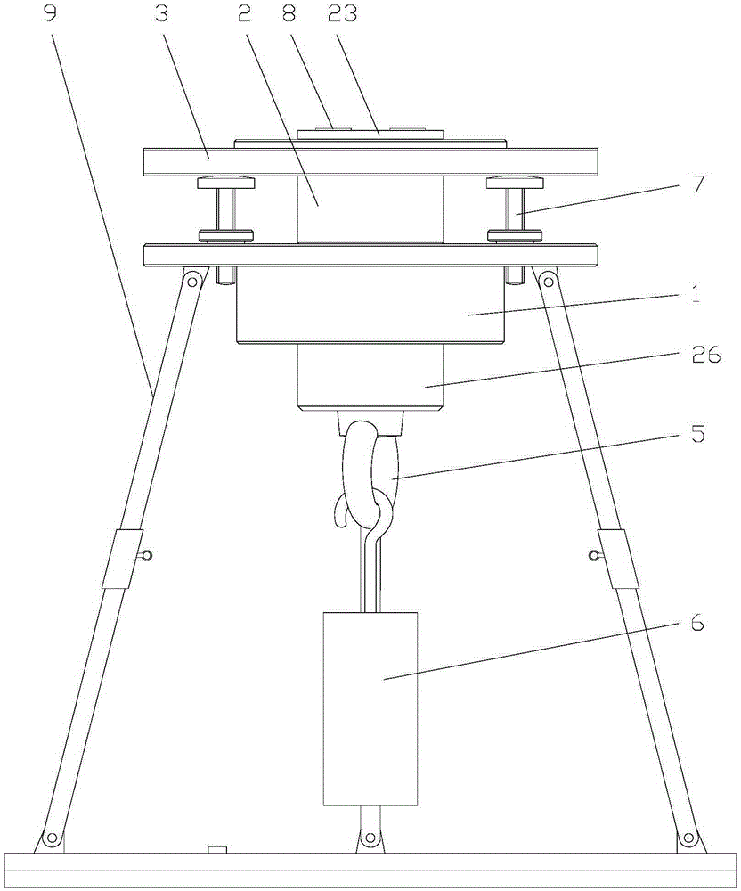
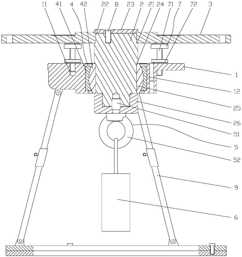
[0019] Such as figure 1 or figure 2 As shown, the present invention includes a bracket 9, a mount 1, a vertical shaft 2 and a horizontal plate 3, the mount 1 is arranged on the bracket 9, the mount 1 is provided with a joint bearing 4, and the bottom of the vertical shaft 2 passes through If it is fixed in the joint bearing 4, the center of the lower end surface of the vertical shaft 2 is provided with a connecting piece 5, the other end of the connecting piece 5 is connected with a counterweight 6, and the upper end of the vertical shaft 2 is vertically fixedly connected with the horizontal plate 3, The mounting base 1 is provided with a plurality of positioning pieces 7 , and the positioning pieces 7 are supported on the bottom surface of the horizontal plate 3 in a height-adjustable manner.

[0020] The positioning member 7 is a bolt 71 , and the bolt 71 is screwed into the positioning hole 11 provided on the mounting base 1 .

[0021] The positioning member 7 is compose...


PUM


Abstract

The invention relates to the technical field of leveling devices, in particular to an automatic leveling device based on a joint bearing and application thereof. The automatic leveling device comprises a bracket, a mounting base, a vertical shaft and a horizontal disc, wherein the mounting base is arranged on the bracket; the joint bearing is arranged in the mounting base; the lower part of the vertical shaft is fixedly inserted in the joint bearing; a connecting piece is arranged in the center place of the lower end surface of the vertical shaft; the other end of the connecting piece is connected with a counterweight block; the upper end of the vertical shaft is vertically and fixedly connected with the horizontal disc; multiple positioning pieces are arranged on the mounting base, are supported on the bottom surface of the horizontal disc in a height adjusting manner, and consist of bolts and nuts; the bolts are inserted in or in threaded connection into positioning holes formed in the mounting base; and the nuts are in threaded connection to the bolts, and are butted against the upper surface of the mounting base. The automatic leveling device is reasonable in design, simple in structure and convenient for use; and no matter which bearing surface is provided with the mounting base and if the mounting base is horizontally mounted, the horizontal disc can be always automatically located in a horizontal state.

Description

technical field [0001] The invention relates to the technical field of leveling devices, in particular to an automatic leveling device based on joint bearings and its application. Background technique [0002] With the development of technology in the technology industry, many measuring instruments (such as range finders, theodolites, etc.), electronic devices (such as projectors, scanners, etc.), and platforms for installing weapons during shooting training, etc., need to be placed On a horizontal plane, but in many cases the bearing surface of the bearing body carrying these instruments is not flat, or some instruments need to be used frequently in different locations, so the state of the bearing surface of the bearing body is constantly changing, and even some instruments It is necessary to work on a moving carrier. The method of making them level in the prior art is usually to manually adjust them and judge them to be in a horizontal state based on experience. This metho...

Claims


Application Information

Patent Timeline
Patent Type & Authority Applications(China)
IPC IPC(8): F16M11/14F16M11/32F41J1/00
Inventor 蔡士源卢同心陈德平陈志雄颜杨丰叶民强施政中
Owner FUJIAN LONGXI BEARING (GROUP) CO LTD
Learn More