Unbalanced-to-balanced converter

a converter and unbalance technology, applied in the direction of electrical equipment, multiple-port networks, coupling devices, etc., can solve the problems of high manufacturing and manufacturing equipment costs, unbalanced-to-balance converters conventions,

Inactive Publication Date: 2000-03-21
MURATA MFG CO LTD
View PDF3 Cites 75 Cited by
  • Summary
  • Abstract
  • Description
  • Claims
  • Application Information

AI Technical Summary

Problems solved by technology

FIG. 2 is a conventional unbalanced-to-balanced converter.
In this situation, advanced manufactur...

Method used


Image

  • Unbalanced-to-balanced converter
  • Unbalanced-to-balanced converter

Examples


Embodiment Construction

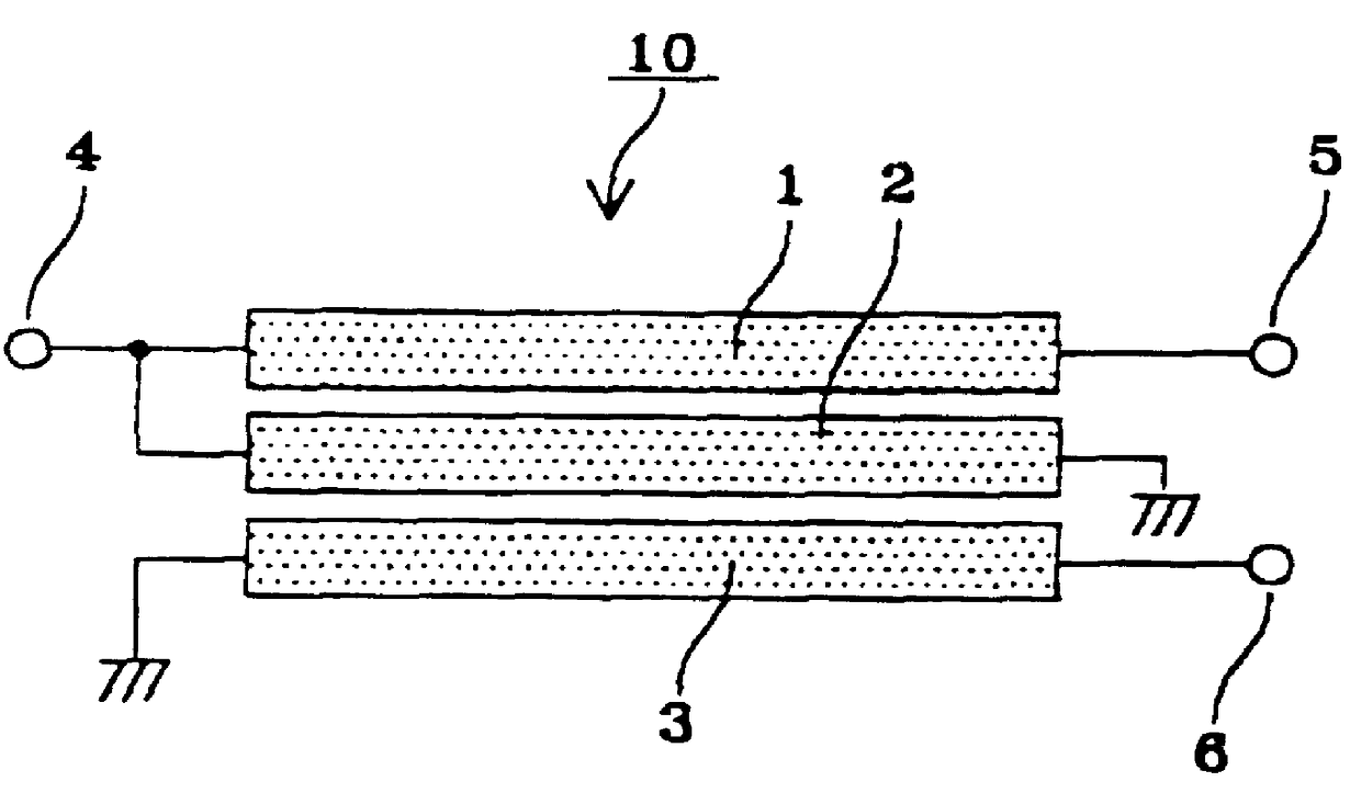
FIG. 1 shows a directional coupler according to an embodiment of the present invention. In FIG. 1, an unbalanced-to-balanced converter 10 includes microstriplines 1, 2, and 3 serving as first, second, and third distributed-constant lines disposed sufficiently close to be coupled with each other, a signal input terminal 4, and signal output terminals 5 and 6.

In FIG. 1, the signal input terminal 4 is connected to the left-hand end of the first microstripline 1 serving as a signal input end, a signal output terminal 5 is connected to the right-hand end of the first microstripline 1 serving as a first signal output end, and a signal output terminal 6 is connected to the right-hand end of the third microstripline 3 serving as a second signal output end. The left-hand ends of the first and second microstriplines 1, 2 are connected to each other, and the right-hand end of the second microstripline 2 and the left-hand end of the third microstripline 3 are grounded.

The microstriplines 1, 2, ...


PUM


Abstract

An unbalanced-to-balanced converter (balun) comprising three distributed-constant lines. In one distributed-constant line, a standing wave is generated. Disposed adjacent thereto is another distributed-constant line to which the power of the standing wave is transferred. A signal input to the unbalanced-to-balanced converter is divided into two signals having phases 180 degrees apart and the same level.

Description

1. Field of the InventionThe present invention relates to unbalanced-to-balanced converters (baluns), and more particularly, to an unbalanced-to-balanced converter used which is usable as a 180-degree phase shifter which divides one signal into two signals having phases 180 degrees apart and having the same level.2. Description of the Related ArtFIG. 2 is a conventional unbalanced-to-balanced converter. In FIG. 2, an unbalanced-to-balanced converter 20 includes three microstriplines 21, 22, and 23 serving as first, second, and third distributed-constant lines disposed sufficiently close to each other that they are coupled with each other, a signal input terminal 24, and signal output terminals 25 and 26.In FIG. 2, the signal input terminal 24 is connected to the left-hand end of the second microstripline serving as a signal input end, a signal output terminal 25 is connected to the right-hand end of the second microstripline serving as a first signal output end, and a signal output ...

Claims


Application Information

Patent Timeline
IPC IPC(8): H01P5/10
CPCH01P5/10
Inventor TANAKA, HIROAKISASAKI, YUTAKAHASHIMOTO, TAKUYA
Owner MURATA MFG CO LTD
Why Eureka
Try Eureka