Clutch mechanism for friction clutch with low declutching force

a friction clutch and low disengagement force technology, applied in the direction of friction clutches, interengaging clutches, clutches, etc., can solve the problems of inability to obtain, the curve shape of the progressive-action device changes very quickly

Inactive Publication Date: 2000-06-27
VALEO MANAGEMENT SERVICES
View PDF13 Cites 10 Cited by
  • Summary
  • Abstract
  • Description
  • Claims
  • Application Information

AI Technical Summary

Problems solved by technology

It is not possible to obtain, during the disengagement travel, an assistance which is as great as desired, the progressive-action device reducing the load exerted by the diaphragm on the thrust plate during this engagement.
The load curves of the progressive-action device and of the diaphragm have shapes which do not make it possible to combine them in order to obtain strong assistance with disengagement, particularly if it is wished to comply with the disengagement travels and forces compatible with the actual disengagement commands.
Moreover, the shape of the curve of the progressive-action device changes very rapidly with the life of the clutch, and the higher the assistance level required, the more this cancels out the disengagement assistance.

Method used


Image

  • Clutch mechanism for friction clutch with low declutching force
  • Clutch mechanism for friction clutch with low declutching force
  • Clutch mechanism for friction clutch with low declutching force

Examples


Embodiment Construction

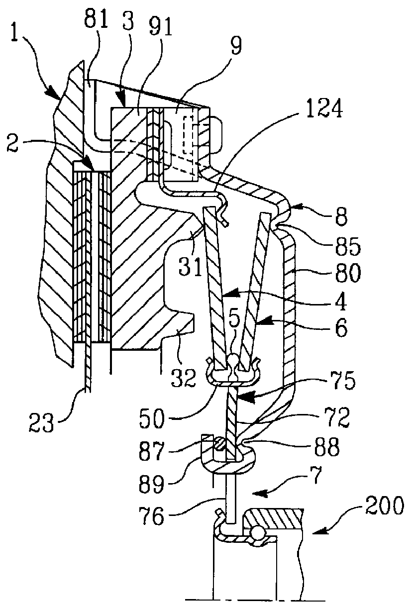
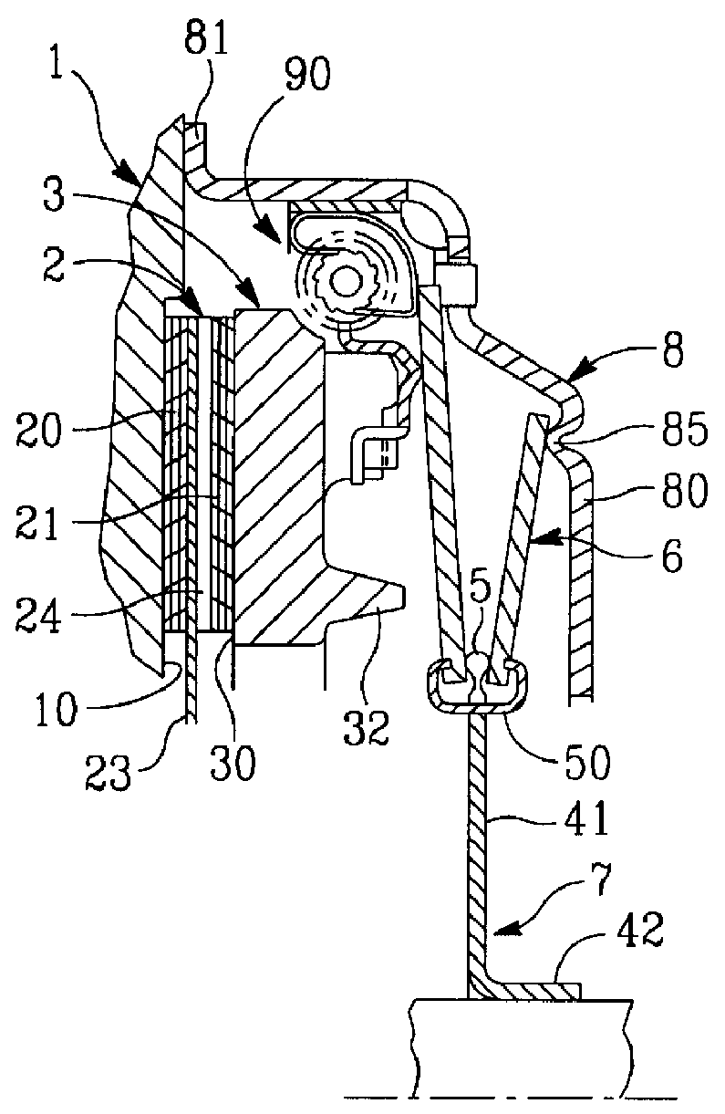
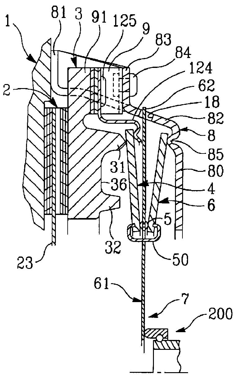
The clutch depicted in FIG. 1 has a set of annular-shaped parts, namely, in succession axially, a flywheel 1 driving in rotation for fixing the clutch to a first shaft, such as a driving shaft, a clutch friction device 2 having at its external periphery friction linings 20, 21 and at its internal periphery a hub, not shown, for rotatably connecting the clutch with a second shaft such as a driven shaft, a thrust plate 3, a first Belleville washer 4, a bearing spring ring 5, a second Belleville washer 6 inclined in the opposite direction with respect to the first Belleville washer 4, a declutching device 7, a hollow-shaped cover 8 having a roughly transversely oriented base 80 with a central hole and, at its external periphery, fixing means 81 for fixing the cover 8 to the flywheel 1 forming a reaction plate.

The flywheel 1 has at its rear a friction face 10 and is depicted here partially, knowing that, in a known fashion, it has centrally holes for fixing it to the driving shaft by me...


PUM


Abstract

PCT No. PCT/FR98/00698 Sec. 371 Date Dec. 4, 1998 Sec. 102(e) Date Dec. 4, 1998 PCT Filed Apr. 7, 1998 PCT Pub. No. WO98/45611 PCT Pub. Date Oct. 15, 1998A clutch mechanism, in particular for motor vehicles, comprising a cover (8) with a base (80), a clutch thrust plate (3) with front friction surface (30) co-operating with a clutch friction (2), and, set between the clutch thrust plate (3) rear surface (36) and the cover (8) base (80), resilient clutch means with axial action (4, 6) axially stressing the clutch thrust plate (3) in a direction opposite to the cover (8) base (80) and a declutching device (7) to counter at will the action of said resilient clutch means (4, 6): the resilient clutch means (4, 6) comprise two Belleville washers (4, 6) series-mounted between the clutch thrust plate (3) and the cover (8), and one (4) of the Belleville washers (4, 6) is in contact at its outer periphery with the clutch thrust plate (3), while the other (6) rests at its outer periphery on the cover (8), said washers (4, 6) sloping inversely, means for transmitting the force (5) carried by the declutching device (7) being incorporated between the inner peripheral zones of the Belleville washers.

Description

1. Field of the InventionThe present invention concerns friction clutches with low disengagement force, notably for motor vehicles, and relates more particularly to the engagement mechanism in such a clutch.2. Description of Related ArtAs is known, in a conventional clutch interposed between a driving shaft and a driven shaft, a diaphragm bears on the base of a cover, fixed to a flywheel for driving in rotation, in order to move a thrust plate in the direction of the flywheel, forming a reaction plate, in order to clamp the friction linings of a clutch friction device between the thrust and reaction plates.The driving flywheel is fixed with respect to rotation to a first shaft, such as a driving shaft, whilst the clutch friction device has at its internal periphery a hub for fixing it with respect to rotation to a second shaft, such as a driven shaft.The clutch is therefore normally engaged, with torque transmission between the driving and driven shafts.In order to disengage, or dec...

Claims


Application Information

Patent Timeline
Patent Type & Authority Patents(United States)
IPC IPC(8): F16D13/58F16D13/75
CPCF16D13/585F16D13/757F16D2013/706F16D2013/581
Inventor DE BRIEL, JACQUES THIRIONGRATON, MICHELDALBIEZ, ANDRE
Owner VALEO MANAGEMENT SERVICES
Why Eureka
Try Eureka