Insulated cup and method of manufacture

a technology of insulated cups and cups, which is applied in the field of disposable cups or containers, can solve the problems of cup wet, cold, and uncomfortable use for prolonged periods of time, and achieves the effects of reducing and increasing the number of disposable cups

Inactive Publication Date: 2000-07-11
GPCP IP HLDG LLC
View PDF43 Cites 122 Cited by
  • Summary
  • Abstract
  • Description
  • Claims
  • Application Information

AI Technical Summary

Problems solved by technology

Polystyrene cups are aesthetically pleasing, but they do not provide much insulation and therefore are only used for holding cold drinks.
Further they are not biodegradable or easily recycled.
Condensation forms on the outside of these cups when holding a cold drink, making the cup wet, cold, and uncomfortable to use for prolonged periods of time.
Also the condensation makes the cup slippery and difficult to hold.
However, they are environmentally unfriendly because they are not biodegradable or easily recyclable.
Also, in order to print these types of cups, a slow and costly printing process must be used, because the cups must be printed after they have been formed, and their rough surface does not allow high-resolution printing.
However they are poor thermal insulators, so that a beverage in a paper cup quickly warms (if cold) or cools (if hot).
They are also uncomfortable to handle because a hot or cold drink can burn or uncomfortably cool a hand.
Also, as with the polystyrene cups, a cold drink will cause condensation to appear on the outside, making a paper cup slippery, and difficult to hold.
Their single-wall construction makes them fragile, so that large cups filled with liquid may crumble after prolonged handling.
This

Method used


Image

  • Insulated cup and method of manufacture
  • Insulated cup and method of manufacture
  • Insulated cup and method of manufacture

Examples


first embodiment

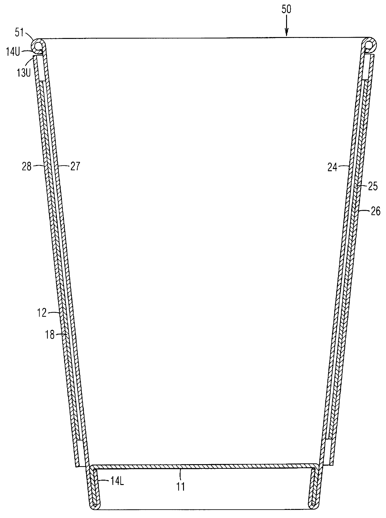
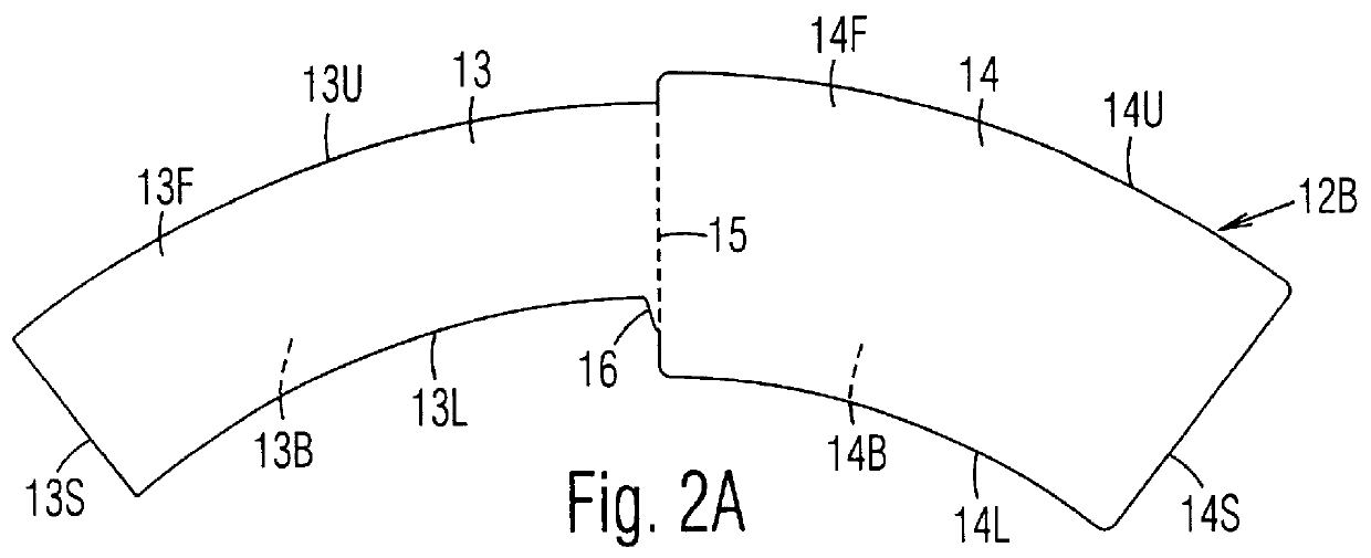
In accordance with the invention a cup or container (FIG. 1), includes bottom 11 and a sidewall 12. The bottom is formed from a bottom blank 11B (FIGS. 2D and 2E). Sidewall 12 is formed from sidewall blank 12B (FIG. 2A), which is die cut from a larger sheet or roll (not shown) of paper or other suitable sheet material. The preferable thickness of this material is approximately 0.33 mm (13 mils), but it can be in a range of 0.2 to 0.6 mm (8 to 24 mils). (One mil=0.001 inch.) The blank includes an arc-shaped left section 13, which will form an outer layer of the sidewall, and an arc-shaped right section 14, which will form an inner layer of the sidewall. The two sections border or share a common fold score 15. The purpose of this fold score is to assist in folding the blank along a precise line. Score 15 is preferably formed into sidewall blank 12B at the time that the blank is die cut from the larger starting sheet. However, the score can be formed into blank 12B after the blank is c...

second embodiment

Foam Coating for Middle Layer

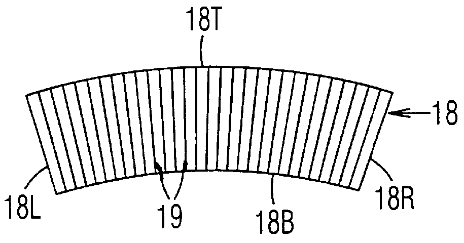
In a second embodiment, the use of a separate insulating sheet is eliminated entirely. It is replaced with a layer of foam which is coated on sections 13F and / or 14F of blank 12B (FIG. 2A) to produce a paper and foam-coated structure similar to that shown in FIG. 10B. In order to provide the layer of foam, section 13F (and / or section 14F) of blank 12B is first coated with a layer of thermoplastic synthetic resin film. The thermoplastic synthetic resin is a low-to-medium density polymer. Such a polymer may include (but is not limited to) polyethylene, polyolefin, polyvinylchloride, polystyrene, polyester, nylon and other similar types of materials. I prefer to use a low-density polyethylene. Opposing sections 13B and 14B of blank 12B are coated with a high-density polyethylene film. Next, blank 12B is heat treated at a temperature and for a time sufficient to permit the low density thermoplastic synthetic resin film to foam and form a heat-insulting layer...

third embodiment

FIGS 11A to 13B

In accordance with a third embodiment, blank 12B and insulating sheet 18 can be replaced with blank 40 (FIG. 11B) to form cup or container 50 (FIG. 1).

Sheet Blanks and Scoring--FIGS 11A TO 11B

Blank 40 (FIG. 11A) is die cut as a single sheet from a larger sheet or roll (not shown) of paper or other suitable sheet material. The preferable thickness of this material is approximately 0.33 mm (13 mils), but it can be in a range of 0.2 to 0.6 mm (8 to 24 mils). Blank 40 is similar to blank 12B (FIG. 2A), except that it has three sections: left section 13, right section 14, and an insulating section 42. Left 13 and right sections 14 share common fold score 15, and are substantially identical to sections 13 and 14 of FIG. 2A. Insulating section 42 (which replaces insulating sheet 18) is connected to section 14 at fold score 41. Section 42 includes upper edge 42U, lower edge 42L, si de edge 42S, front side 42F and back side 42B. Sec tions 13, 14 and 42 will form respective out...


PUM


Abstract

An insulating cup or container (50) and a method of manufacturing it comprises (first embodiment) providing a sidewall blank (12B) having two sections separated by a fold score (15), and a separate insulating sheet (18)(corrugated, ribbed, embossed, foamed, perforated, etc.) which is adhesively fastened to one of the sections. Adhesive is applied to an area (21) adjacent the fold score. The blank is folded in half along the fold score, to form a three-layered assembly with the insulating sheet in the middle. The adhesive that was applied adjacent the fold score bonds the two sections together at an area (21) adjacent a fold edge (22) on the inside surfaces of the folded blank. The assembly is wrapped around a mandrel to bring the outer edges together at a sideseam (22S) to form a sidewall 12. The side seam is sealed, the bottom is added, and the rim is formed. The placement of the adhesive is critical, in that it holds the blank in its folded state and allows it to be wrapped properly at high production speeds. In a second embodiment, the insulating layer can be a coating on one or both of the sections of the two-section starting blank. In a third embodiment, the insulating section (40) can be integral with, and extend from, one edge of the starting blank. It is folded over first to form the middle layer of the wrappable assembly.

Description

BACKGROUND--CROSS-REFERENCE TO RELATED CASESThis invention is an improvement on the inventions in U.S. Pat. No. Re.35,830 (Jun. 30, 1998) to C. E. Sadlier, and U.S. Pat. Nos. 5,660,326 (Aug. 26, 1997) and 5,697,550 (Dec. 16, 1997) to R. Varano and C. E. Sadlier.BACKGROUND--FIELD OF INVENTIONThis invention relates generally to disposable containers and specifically to an insulated disposable cup or container and a method of manufacture.BACKGROUND--PRIOR ARTThere are three main types of disposable cups now in use: polystyrene, expanded polystyrene, and paper.Polystyrene cups are aesthetically pleasing, but they do not provide much insulation and therefore are only used for holding cold drinks. Further they are not biodegradable or easily recycled. Condensation forms on the outside of these cups when holding a cold drink, making the cup wet, cold, and uncomfortable to use for prolonged periods of time. Also the condensation makes the cup slippery and difficult to hold.Cups made from ex...

Claims


Application Information

Patent Timeline
IPC IPC(8): B65D3/22B65D3/28B65D81/38B65D3/00
CPCB65D3/22B65D3/28B65D81/3869B65D81/3874Y10S229/939Y10S493/907
Inventor SADLIER, CLAUS E.
Owner GPCP IP HLDG LLC
Why Eureka
Try Eureka