Connector security mechanism

a security mechanism and connector technology, applied in the direction of electrical equipment, contact members penetrating/cutting insulation/cable strands, coupling device connections, etc., can solve the problem of no security mechanism in the connector top section to prevent or hinder unauthorized opening of the connector

Inactive Publication Date: 2000-08-15
AVAYA TECH CORP
View PDF9 Cites 23 Cited by
  • Summary
  • Abstract
  • Description
  • Claims
  • Application Information

AI Technical Summary

Problems solved by technology

The prior art connector has no security mechanism to prevent or hinder unauthorized opening of the connector top section.
Also, because there is no security mechanism on the prior art connectors, an authorized user may simply inadvertently open up a connector with out even knowing it.

Method used


Image

  • Connector security mechanism
  • Connector security mechanism
  • Connector security mechanism

Examples


Embodiment Construction

Generally speaking, in accordance the instant invention, a connector security mechanism is provided which hinders unauthorized opening of a connector and / or minimizes accidental opening of connectors.

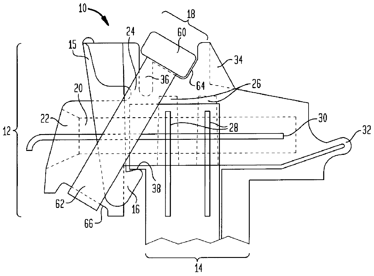
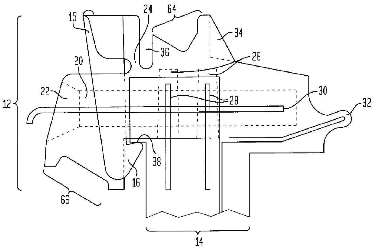
In a preferred embodiment, as seen in FIGS. 1 and 2, a connector of the present invention, generally indicated as 10, has a top section, generally indicated as 12, movable between an open position and a closed position, and a bottom fixed section, generally indicated as 14. Connector 10 generally comprises two entrance apertures 22 which lead to wire insertion holes 20. Wire insertion holes 20 are constructed so as to accept wires 30. Connector 10 also has terminal strip receiving portions 26, which are constructed to accept terminal strips 28 when the top section 12 is in its closed position.

As seen in FIG. 3, when top section 12 is in its open position, terminal strips 28 do not intersect wire insertion holes 20, and when top section 12 is in its closed position (FIG. 2), terminal str...


PUM


Abstract

A tool-less insulation displacement connector comprising a top section and a bottom section, the top section being movable between an open position and a closed position; a latch member movable between an engaged position and a disengaged position, the latch member maintaining the top section in the closed position when the latch member is in the engaged position; and a releasable security member for preventing the latch member from moving between the engaged position and the disengaged position.

Description

This invention relates to a wiring connector, and in particular, to a connector having a security mechanism.BACKGROUND OF INVENTIONIn a telephone network, a network cable from the central office is connected to a building entrance protector (BEP) located at the customer site, where the individual telephone lines are broken out line by line. The network cable, which consist of a plurality of tip-ring wire pairs that each represent a telephone line, is typically connected to a connector block that is an integral part of the BEP. Such connectors may be, for example, the ubiquitous 66-type punch down connector, or an SC 99 type connector block, such as are available from Lucent Technologies Inc., or the mini-rocker tool-less insulation displacement (IDC) type connector, such as for example those sold by A. C. Egerton, Ltd. Other connectors used for telephony wiring applications are described in U.S. Pat. No. 4,662,699 to Vachhani et al., dated May 5, 1987, and in U.S. Pat. No. 3,611,264...

Claims


Application Information

Patent Timeline
Patent Type & Authority Patents(United States)
IPC IPC(8): H01R13/639H01R4/24
CPCH01R13/6397H01R4/24
Inventor DAOUD, BASSEL H.
Owner AVAYA TECH CORP
Why Eureka
Try Eureka