Safety gate for children

Inactive Publication Date: 2000-09-05
CHENG SHU CHEN
View PDF11 Cites 81 Cited by
  • Summary
  • Abstract
  • Description
  • Claims
  • Application Information

AI Technical Summary

Problems solved by technology

However, if the children are tall enough to reach the lock (56), the lock (56) might be accidentally unlocked, and either the first plate body (52) or the second plate body (54) will be opened, which will compromise the integrity and usefulness of the gate (50).
Because the existing safety gate cannot fully protect children from accident

Method used


Image

  • Safety gate for children
  • Safety gate for children
  • Safety gate for children

Examples


Embodiment Construction

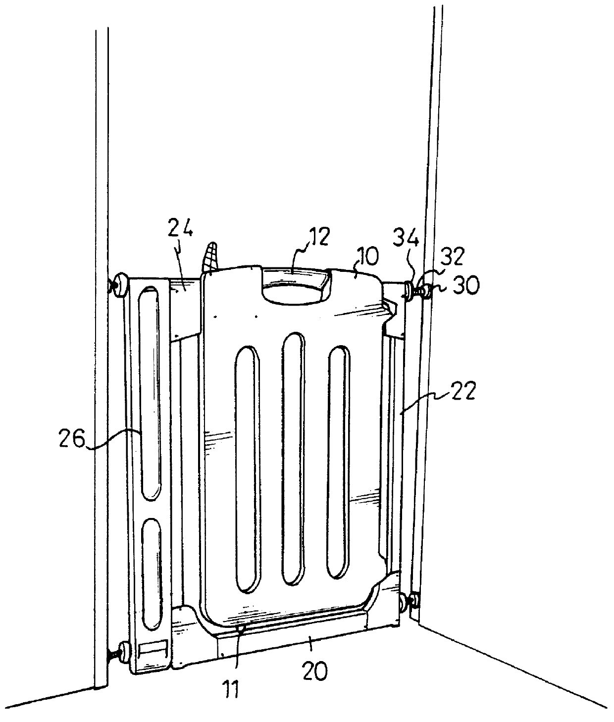
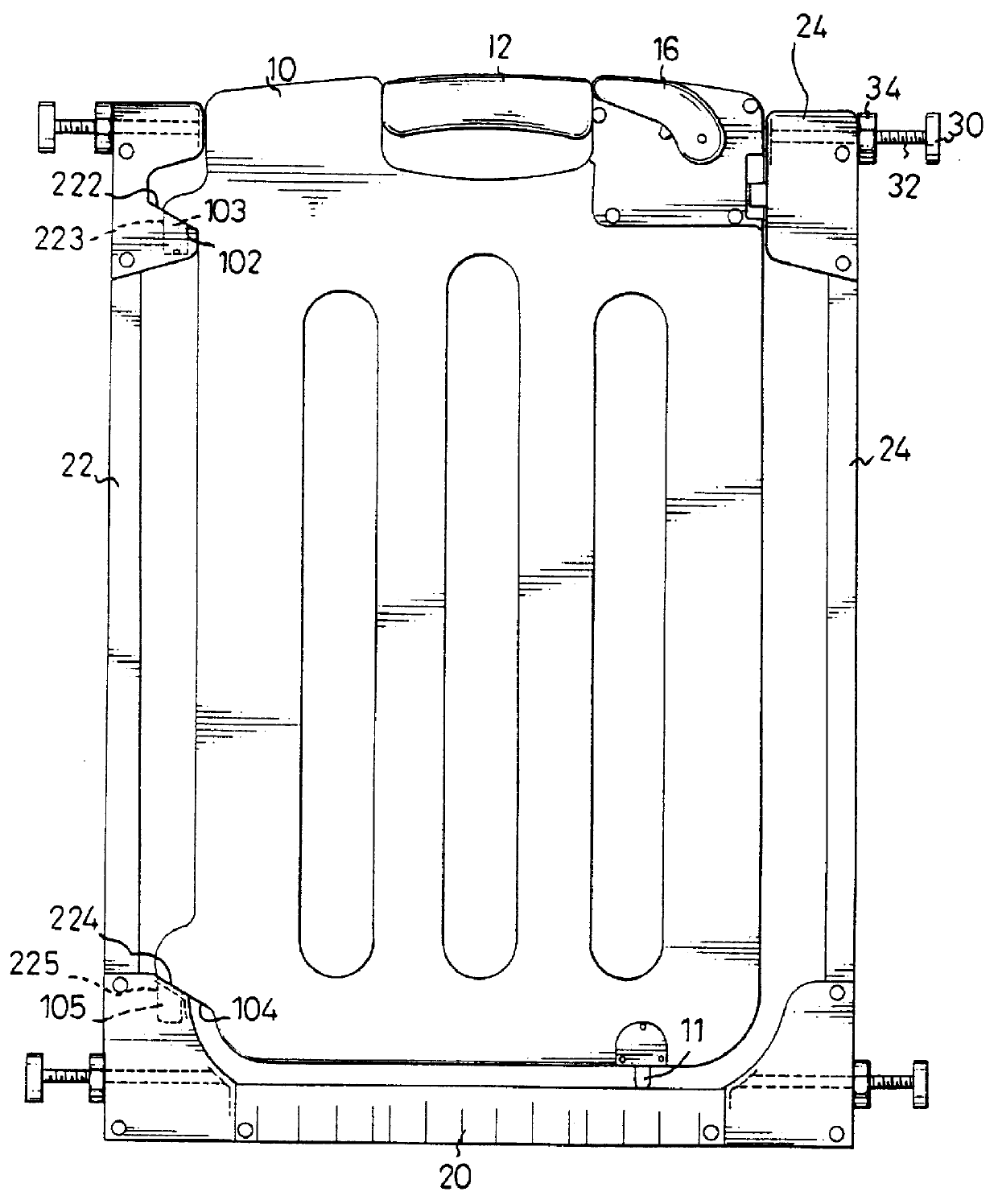
The present invention relates to a safety gate. As shown in FIGS. 1 and 2, the safety gate has a plate body (10), a base (20) detachably engaged with the plate body (10), a first side bar (22) detachably engaged with the plate body (10), a second side bar (24) pivotally engaged with the plate body (10) and a lock provided in the plate body (10). The plate body (10) has two opposed inclined faces (102, 104) respectively formed on the side connected with the first side bar (22) and each of the inclined faces (102, 104) has a downward extending lug (103, 105) formed thereon. The first and second side bars (22, 24) are securely connected with the base (20), and each has a pair of adjusting devices (30) securely connected therewith. The adjusting device (30) has two bolts (32) securely inserted into the first and the second side bars (22, 24) and a nut (34) threadingly movable on the bolt (34). By adjusting the bolts (32) of one pair of adjusting devices (30) on the second side bar (24) ...


PUM


Abstract

A safety gate for a doorframe, which is able to prevent small children from going into a restricted or dangerous area, has a lock that requires two different and independent steps to proceed the unlock process. Furthermore, after the lock is unlocked, the user still needs to lift the plate body before the pivotal movement of the plate body with respect to the first side bar is possible.

Description

1. Field of the InventionThe present invention relates to a safety gate for children and especially for a safety gate having a locking device provided therein, so as that the safety gate is able to protect the children from accidentally going into a restricted or dangerous area.2. Description of Related ArtAs shown in FIG. 11, a conventional safety gate (50) for children is shown. The safety gate (50) normally has a first plate body (52) detachably engaged with a side of the doorframe and a second plate body (54) slidably engaged with the first plate body (52). The first plate body (52) has a lock (56) provided to secure the movement of the second plate body (54) with respect to the first plate body (52) and a plurality of protrusions (58) formed on a side face thereof, such that when the first plate body (52) engages with the side of the doorframe, the protrusions (58) are able to be received in the corresponding recesses (not shown) in the doorframe to secure the engagement thereb...

Claims


Application Information

Patent Timeline
IPC IPC(8): E06B9/02E06B9/04
CPCE06B9/04E06B2009/002Y10S292/12
Inventor CHENG, SHU-CHEN
Owner CHENG SHU CHEN
Why Eureka
Try Eureka