Snap in cable connector

a technology of cable connectors and clamps, which is applied in the direction of casings/cabinets/drawers, casings/cabinets/drawers, electrical apparatus, etc., can solve the problems of increasing the complexity of fittings, and achieve the effect of convenient us

Inactive Publication Date: 2000-09-05
ARLINGTON INDS
View PDF7 Cites 107 Cited by
  • Summary
  • Abstract
  • Description
  • Claims
  • Application Information

AI Technical Summary

Problems solved by technology

This presented problems with the screw penetrating the insulation covering on the wire.
As the snap type fittings are constructed of several pieces, the complexity of the fitting is increased.

Method used


Image

  • Snap in cable connector
  • Snap in cable connector
  • Snap in cable connector

Examples


second embodiment

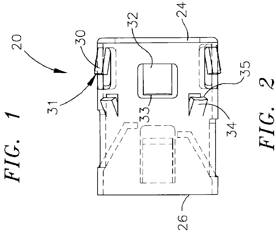
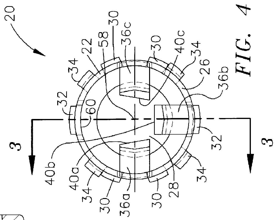
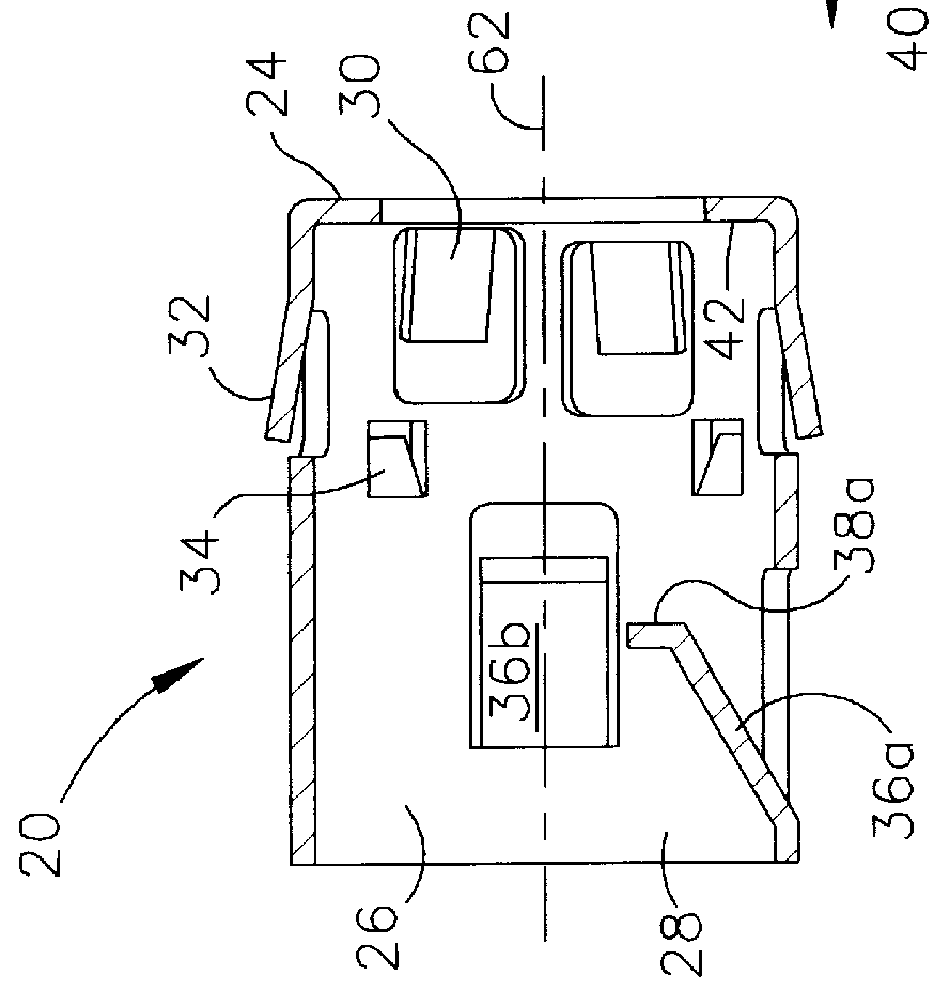
The second embodiment is different from the preferred embodiment by the mechanism which stops forward travel of the connector into a junction box, which for the second embodiment is a central flange 72 around the periphery of the tubular body 22. When inserted into a junction box, the securement tangs 30 are first contacted by the inside periphery of a knock-out, are depressed inwardly, and spring out again when clear of the junction box wall. The grounding tangs are depressed and remain depressed against the inner periphery of the knock-out to maintain a ground between the junction box and the connector. Forward travel of the one-piece snap-in electrical connector is stopped when the wall of the junction box (not shown) contacts the forward face 74 of the central flange 72. The distance between the ends 31 of the securement tangs 30 and the forward face 74 of the central flange 72 define a seat 76 within which the inner periphery of the knock-out (not shown) will rest after the sec...


PUM


Abstract

A one-piece tubular snap-in electrical connector for connecting electrical cables to junction boxes. The connector is formed from an elastic material and includes tangs projecting outwardly from the tubular body which function to lock the forward end in a junction box and cause the connector to be grounded to the junction box. Inward projecting tangs on the opposite end of the connector are spaced to anchor successive helixes on a helically-wound cable. The ends of the inward projecting tangs force an inserted cable to be channeled against one inner wall of the tubular body and resist rearward movement of the cable once it is thus inserted.

Description

FIELD OF THE INVENTIONThis invention relates to cable terminations and more particularly to locking cable terminations which snap into place and require no screws or twisting for locking.BACKGROUND OF THE INVENTIONAn extensive number of various types of cable connectors have been designed since the initial use of electricity prior to the turn of the century. Many types are still in use in some form. The most common initial design that is in use today is a type that was first patented in the mid-twenties. This type includes a screw that is tightened once the cable or electrical wire is in place. The electrical cable is fed into a hole or slot in a junction box through an oversized fitting that has provision for receiving a screw. In the early design the screw was configured to press directly against the electrical cable. This presented problems with the screw penetrating the insulation covering on the wire.Presently, one screw type securement is where the screw tightens a clamp that ...

Claims


Application Information

Patent Timeline
Patent Type & Authority Patents(United States)
IPC IPC(8): H05K13/00
CPCH05K13/00
Inventor GRETZ, THOMAS J.
Owner ARLINGTON INDS
Why Eureka
Try Eureka