Wellbore wash nozzle system

a technology of wash nozzles and wash nozzles, which is applied in the direction of movable spraying apparatus, borehole/well accessories, fluid removal, etc., and can solve problems such as inhibiting or preventing effective operation

Inactive Publication Date: 2001-02-20
WEATHERFORD TECH HLDG LLC
View PDF36 Cites 180 Cited by
  • Summary
  • Abstract
  • Description
  • Claims
  • Application Information

AI Technical Summary

Benefits of technology

The present invention, in certain aspects, discloses a wash nozzle having a central mandrel with a fluid flow bore therethrough from top to bottom. Initially a piston is sealingly and releasably secured within the fluid flow bore

Problems solved by technology

In wellbore milling, drilling, and milling-drilling operations cuttings are produced which, if not efficien

Method used


Image

  • Wellbore wash nozzle system
  • Wellbore wash nozzle system
  • Wellbore wash nozzle system

Examples


Embodiment Construction

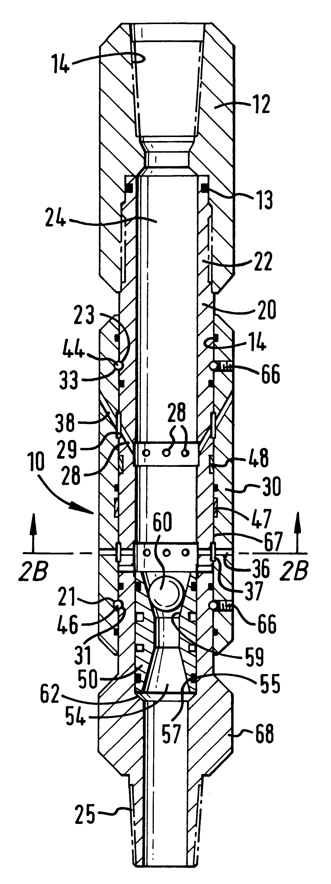
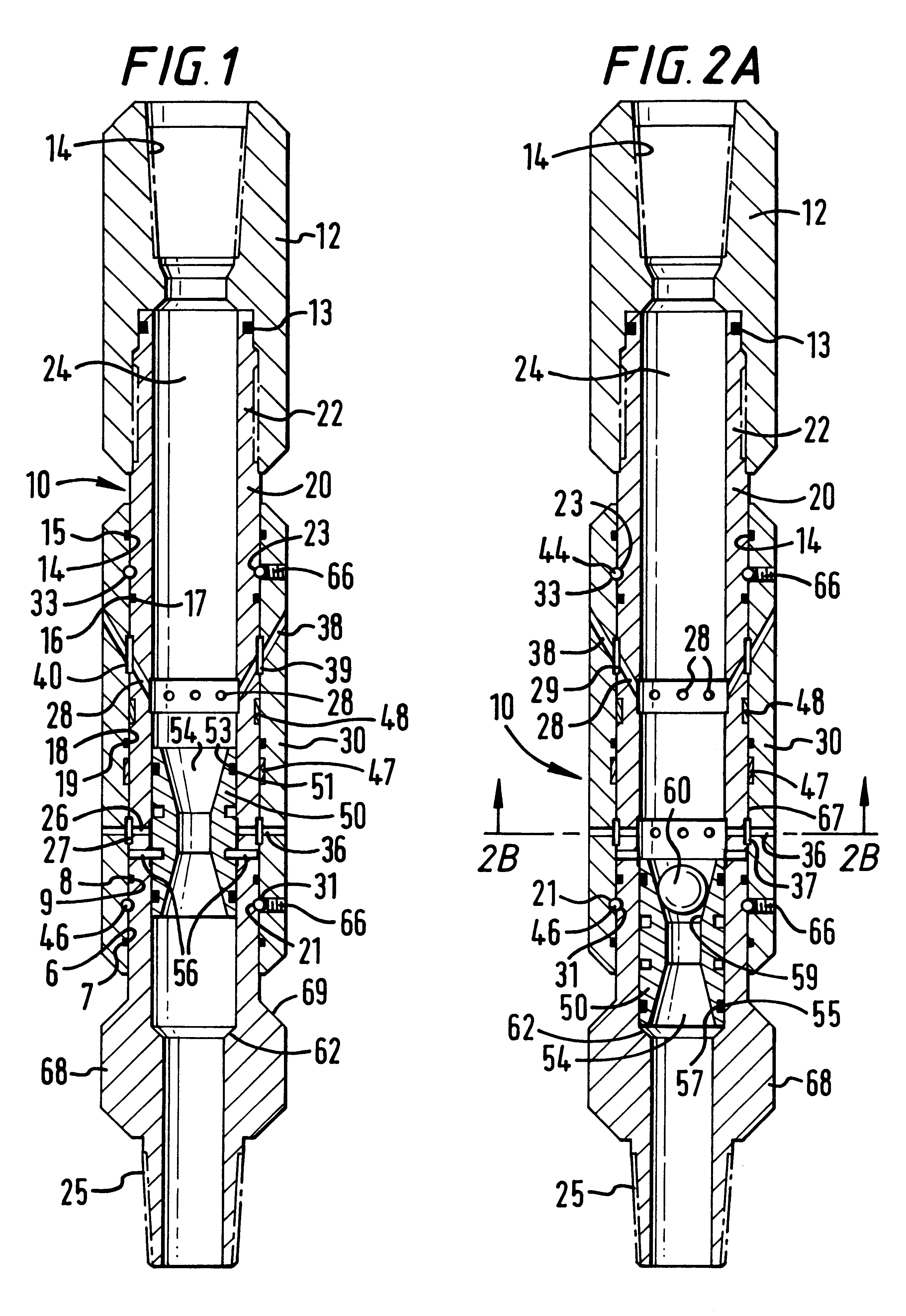
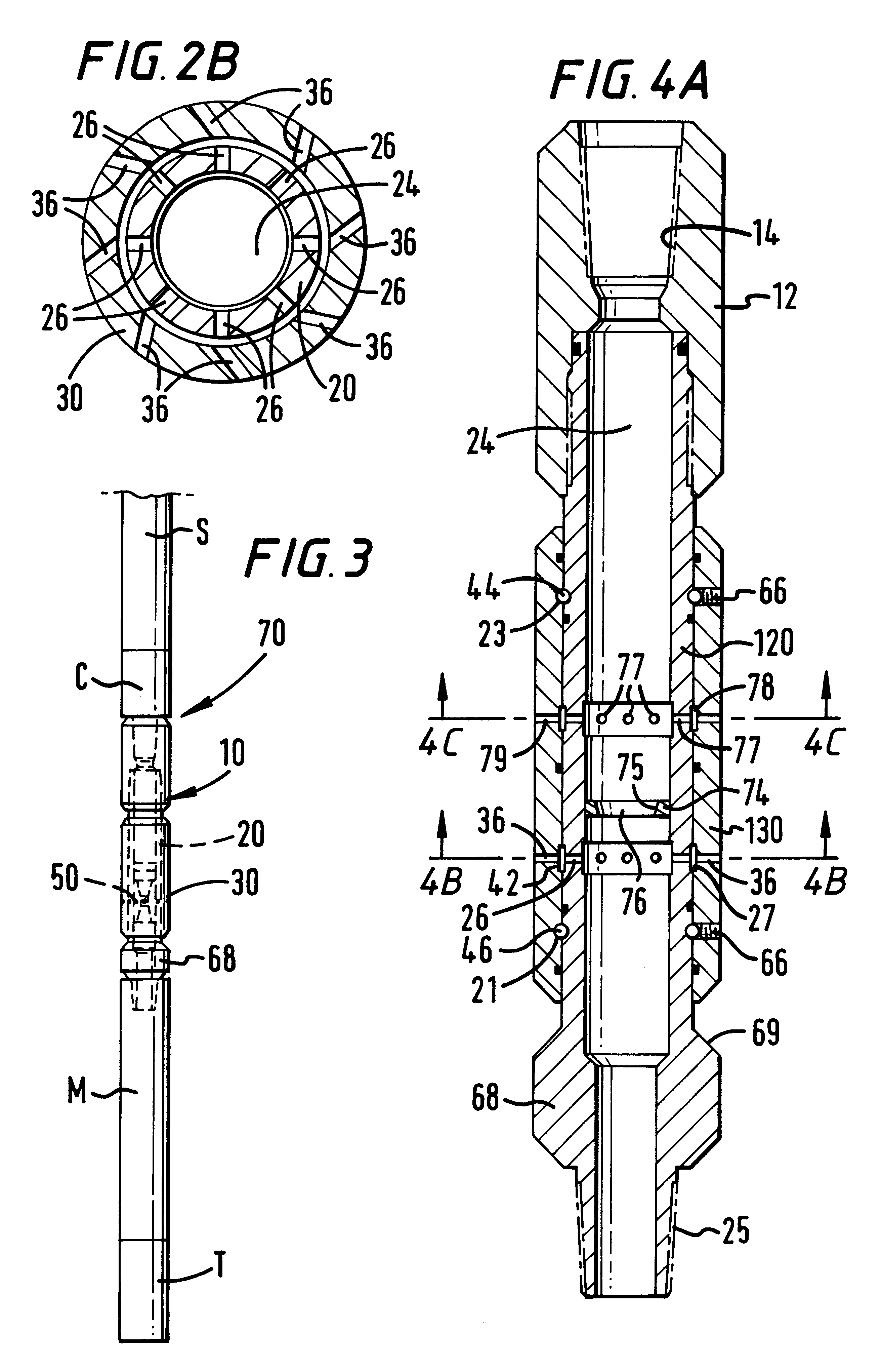
FIGS. 1 and 2A show a wash nozzle 10 according to the present invention with a central mandrel 20 having a top sub 12 threadedly connected to a top 22 of the central mandrel 20 and a sleeve 30 with a bore 67 therethrough rotatably mounted around the exterior of the central mandrel 20. The top sub 12 is connectible to any other suitable wellbore apparatus, device, tubular, or tubular string. In one aspect the top sub 12 is sized to act as a top stabilizer for the nozzle 10. Alternatively a stabilizer and / or centralizer is attached to or formed of the top and / or bottom of the mandrel 20.

Fluid pumped from the surface down a string to which the top sub 12 is connected flows through a fluid flow bore 14 through the top sub 12 and through a fluid flow bore 24 from the top 22 of the central mandrel 20 to and out through a bottom 25 of the central mandrel 20.

An O-ring 13 seals an interface between the interior of the top sub 12 and the exterior of the central mandrel 20. An O-ring 14 in a r...


PUM


Abstract

A wash nozzle for wellbore washing operations has been invented, the wash nozzle, in one aspect having a central mandrel with a top, a bottom, and a fluid flow bore therethrough from top to bottom, at least one mandrel port through the central mandrel for fluid flow from within the central mandrel's fluid flow bore to an exterior of the central mandrel, a hollow sleeve rotatably mounted around the central mandrel, and at least one sleeve port through the sleeve for fluid flow from within the sleeve from the exterior of the central mandrel to an exterior of the sleeve, the at least one sleeve port defined by a wall on the sleeve. In one aspect the wash nozzle includes apparatus for selective rotation of the sleeve about the mandrel. In one aspect flow through the wash nozzle is stopped to effect sleeve rotation and, in one particular aspect, flow through the nozzle is then re-established. Methods have been invented using such wash nozzles for wellbore washing operations and/or cuttings removal.

Description

1. Field of the InventionThis invention is directed to wellbore wash nozzles; to wellbore apparatuses and systems for facilitating the flow of cuttings from a wellbore mill, drill or mill-drill; in certain aspects, to milling, drilling, or milling-drilling systems with a wash nozzle; and to methods for using such nozzles and systems.2. Description of Related ArtIn wellbore milling, drilling, and milling-drilling operations cuttings are produced which, if not efficiently removed from the area around a mill, drill, or mill-drill, will inhibit or prevent effective operation. Typically such cuttings are removed by fluid pumped from the surface down through a work string, tubing string, or coiled tubing, through various apparatuses and devices, to the location of milling, drilling, or milling-drilling. In many prior art systems fluid is pumped through ports in a nozzle, mill, drill, or mill-drill. The pumped fluid moves the cuttings away from wellbore tools and up in an annulus in the we...

Claims


Application Information

Patent Timeline
IPC IPC(8): E21B37/00
CPCE21B34/14E21B37/00B05B3/027B05B3/06E21B34/142
Inventor BEEMAN, ROBERT S.LEE, MARKMCCLUNG, III, GUY L.BREAUX, STEPHEN P.
Owner WEATHERFORD TECH HLDG LLC
Why Eureka
Try Eureka