Flexible bearing cage

a bearing cage and flexible technology, applied in the field of cages, can solve the problems of retaining cages that are difficult to install, protruding members that cannot be fixed, and failure of retaining cages, etc., and achieve the effect of convenient feeding into or wrapping

Inactive Publication Date: 2001-06-19
HARKEN INC +1
View PDF20 Cites 74 Cited by
  • Summary
  • Abstract
  • Description
  • Claims
  • Application Information

AI Technical Summary

Problems solved by technology

The bearing cages as disclosed in these patents and as otherwise known in the art, however, have in common heretofor unresolved problems.
Such bearing retaining cages may be difficult to install, particularly if they are circular and include a protruding member for insertion into a slot on one of the inner or outer races.
Snap fitting of the cages, however, can lead to failure of the retaining cage or of the protruding member.
Further, for applications having a race that is not circular shaped but is instead oval or otherwise features an oddly shaped race, bearing retaining cages as presently known may not be appropriate.

Method used


Image

  • Flexible bearing cage
  • Flexible bearing cage
  • Flexible bearing cage

Examples


Embodiment Construction

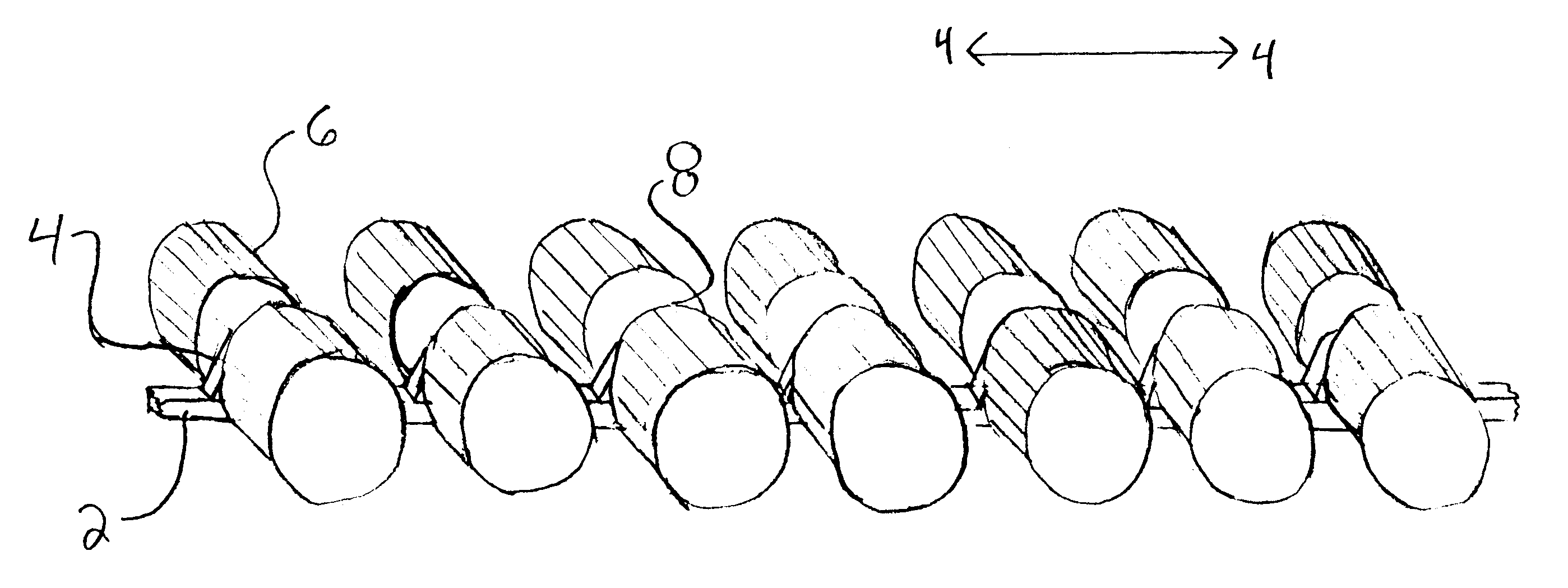
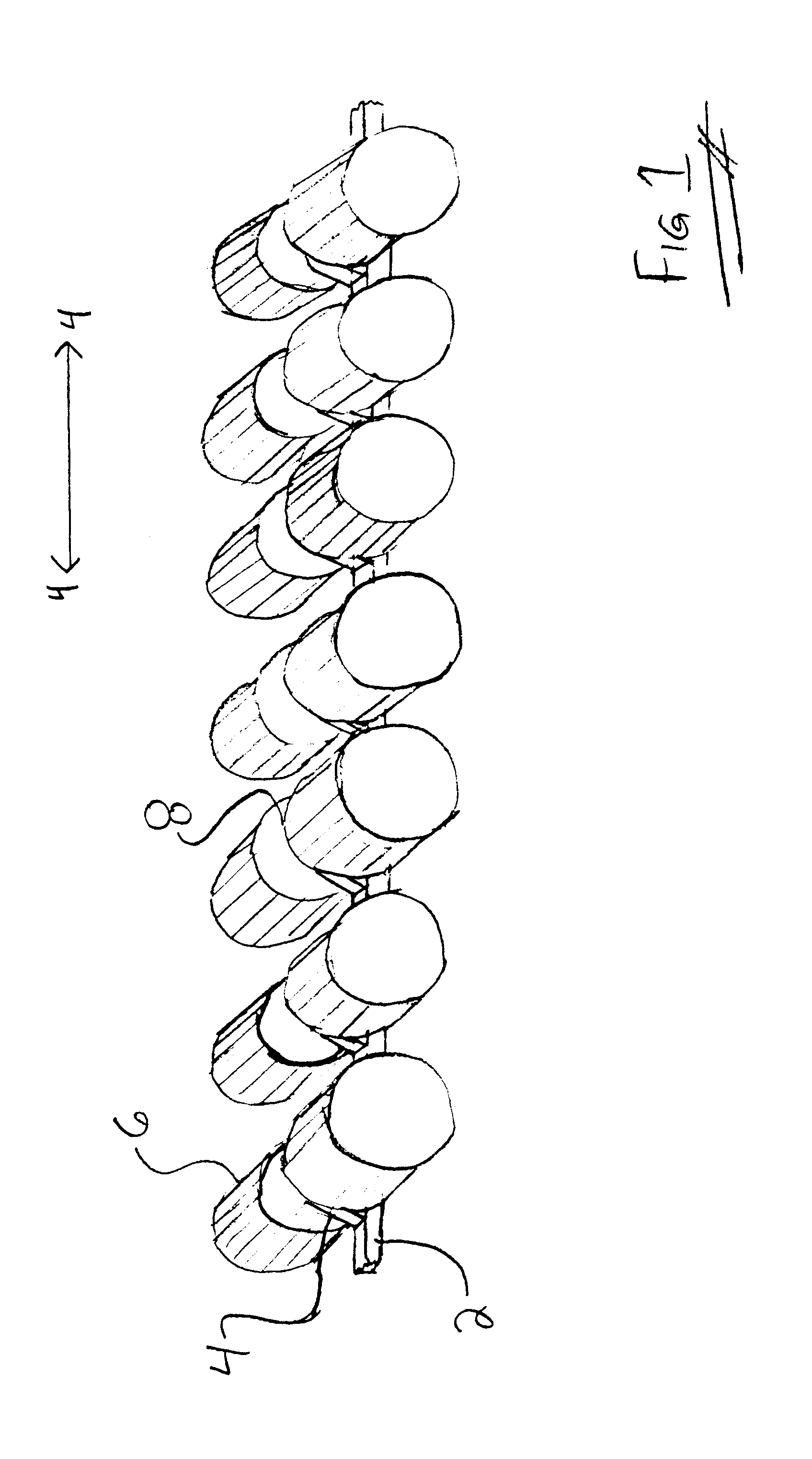
Turning now to the drawings, FIG. 1 is a perspective of a preferred flexible bearing cage assembly embodiment of the invention. Flexible spine 2 has a plurality of resilient notch arms 4 which define a notch therebetween for snap fitting roller bearings 6. Roller bearings 6 have an annular recessed ring 8 about their center for receiving notch arms 4. Roller bearings 6 are rotatably held in place between notch arms 4, so that they may freely rotate.

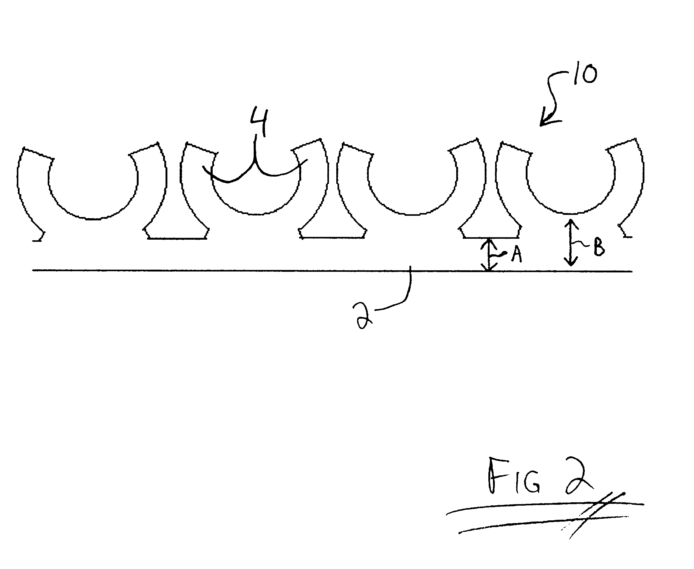
FIG. 2 is a transverse view of the preferred flexible cage 10 of the invention with flexible spine 2, and with notch arms 4 for receiving roller bearings therebetween. FIG. 3 is a transverse view of preferred flexible cage 10 bent in an arcuate shape with roller bearings 6 snap fit into place about spine 2. As discussed infra, flexible spine 2 may be bent to form a variety of shapes, including, bot not limited to, circular, linear, elliptical, angular, and oval; and may be cut from bulk to a desired length to fit a race of a given dimensi...


PUM


Abstract

A flexible bearing retaining cage has a flexible spine with bearing retaining means for rotatably retaining bearings. A flexible bearing cage assembly comprises a flexible bearing retaining cage with bearings rotatably retained. The flexible cage of the invention may be configured in a variety of shapes including, but not limited to, linear, oval, eliptical, and circular. The cage of the invention may also be cut to a desired length to fit a particular race.

Description

FIELD OF THE INVENTIONThe present invention relates to cages for rotatably retaining bearings, aligning the bearings, and for separating them from one another.BACKGROUND OF THE INVENTIONBearing retaining cages retain bearings such that the bearings are held in place but are allowed to freely rotate. Generally, the cages are circular or linear. In this manner a bearing cage may be used to hold bearings in alignment with one another and to keep the bearings separate from one another so that they do not rub against one another. The bearings may be contained between an inner and outer race to facilitate relative movement of one about the other. Bearing cages may also include a protruding member for alignment in a slot along a race to align the bearings and to limit their movement in a direction perpendicular to the slot.Examples of bearing retaining cages include those as disclosed in U.S. Pat. Nos. 1,018,324 to Kempster; 2,016,526 to Tyson; 3,980,359 to Weatherbee; and 5,154,401 to Sch...

Claims


Application Information

Patent Timeline
Patent Type & Authority Patents(United States)
IPC IPC(8): F16C33/30F16C33/36F16C33/46F16C33/54F16C19/22F16C19/28F16C19/26F16C33/49F16C33/52
CPCF16C19/26F16C33/36F16C33/4605F16C33/498F16C33/506F16C33/52F16C33/543F16C33/363
Inventor LOB, CHARLES J.
Owner HARKEN INC
Why Eureka
Try Eureka