Self-locking orthodontic bracket

a self-locking, orthodontic technology, applied in the field of self-locking orthodontic brackets, can solve the problems of affecting the movement of teeth, friction between the brackets and the arch wire, and ligatures that make proper oral hygiene more difficult, etc., to achieve the effect of reducing the time taken, convenient use and convenient fabrication

Inactive Publication Date: 2001-06-19
VASHI NIKHIL SHANKARLAL
View PDF22 Cites 101 Cited by
  • Summary
  • Abstract
  • Description
  • Claims
  • Application Information

AI Technical Summary

Problems solved by technology

Placement of these small wires or elastomeric ligature rings requires considerable time during initial installation of an arch wire.
Ligatures also tend to make proper oral hygiene more difficult as the wires can trap food particles, and the twisted ends of a ligature may be shifted during cleaning into a position where irritation of the patient's gums or cheek tissues occurs.
Since the ligature ties are in firm contact with the arch wire, friction is generated between the brackets and the arch wire affecting the tooth movements adversely.
The other means are more complex, however, and therefore difficult and expensive to manufacture Also, they are not as compact as would be desired.
Additionally, it is difficult to use auxiliary attachments with brackets without tie wings.
Also, with brackets having detachable parts, there are chances of such parts getting separated accidentally and getting lost or swallowed by patients.
Moreover, springs used as locking means are not strong enough to hold the arch wire into the slot.

Method used


Image

  • Self-locking orthodontic bracket
  • Self-locking orthodontic bracket
  • Self-locking orthodontic bracket

Examples


Embodiment Construction

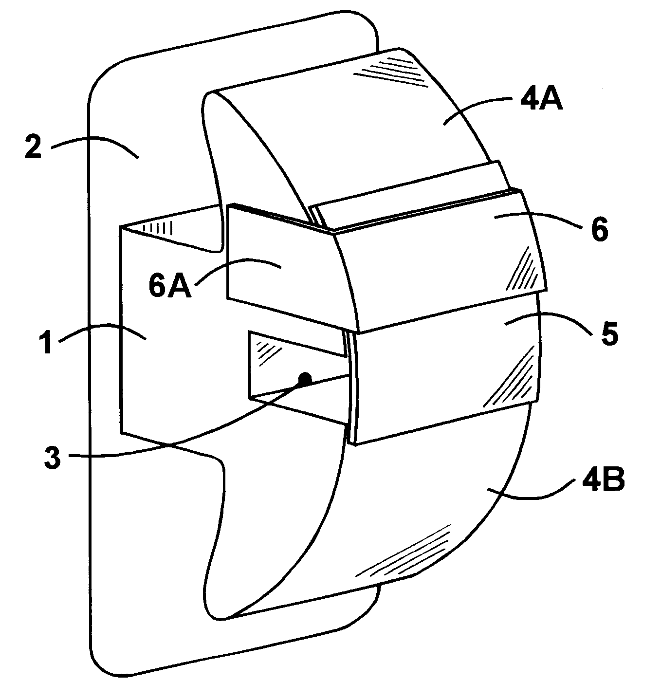
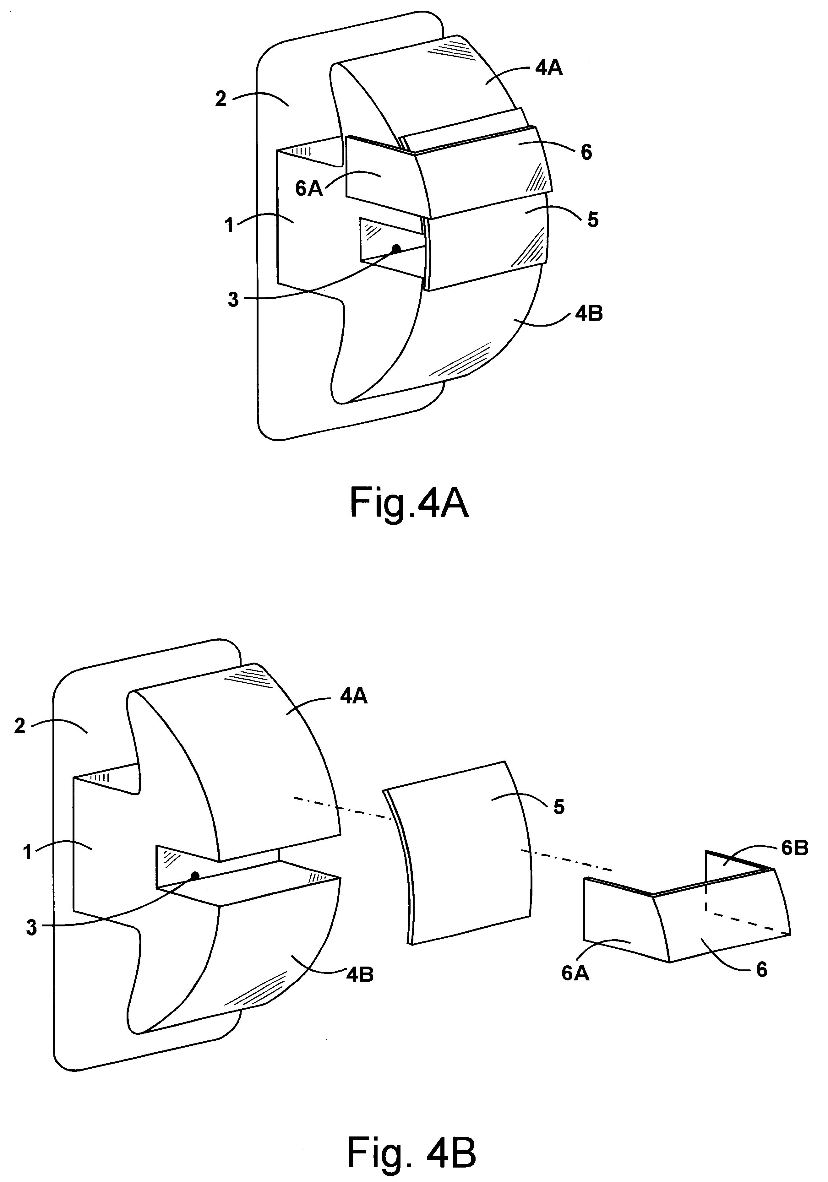
The following describes the embodiments of present invention as illustrated in FIGS. 4A to 32.

FIGS. 4A, 4B, 5, and 6 show a self-locking orthodontic bracket of the invention. The bracket includes a body 1 that is attached to a base 2. The body of the bracket can be of metal, plastic, ceramic or of any other permissible material. The base 2 is contoured to fit a tooth surface and can be bonded directly to a tooth or can be attached to a band material. The body 1 of the bracket has an arch wire slot 3 extending horizontally across the labial / buccal surface to engage arch wires during orthodontic treatment to exert pressure. At least one tie wing 4A projects out vertically from the body 1, which may be of a gingivally-projecting or occlusally-projecting nature. Another tie wing 4B may extend out vertically opposite to the tie wing 4A. These are used for the attachment of auxiliaries like elastic chains and ligature wires. A retainer member 6 having a transverse part and two horizontal ...


PUM


Abstract

A self-locking orthodontic bracket comprises a body (1) and a base (2) contoured to fit a tooth surface. The body (1) has an arch wire slot (3) extending horizontally across the labial / buccal surface, a pair of tie wings (4A and 4B) projecting vertically on either side of the arch wire slot (3), a retainer member (6) having a transverse part and two perpendicular horizontal extensions at the end (6A and 6B) attached to the sides of one of the tie wings (4A) and a slidable cover (5) retained and guided in the recess created between the retainer member (6) and the surface of the tie wing (4A). The slidable cover (5) can be moved vertically towards the tip of the tie wing (4A) to open the arch wire slot (3) and it can be moved in the opposite direction to close the arch wire slot (3).Different embodiments of the slidable cover (5) and the retainer member (6) are disclosed herein.

Description

This invention relates to self-locking or ligatureless orthodontic brackets.Orthodontic brackets may be used with arch wires to straighten irregular teeth. These brackets are attached to the teeth and engage a flexible arch wire that exerts pressure upon them to move the teeth. The most commonly used brackets are edgewise brackets as shown in FIGS. 1, 2, and 3. FIG. 1 shows a Siamese twin bracket, FIG. 2 shows a single bracket with rotation wings, and FIG. 3 shows a modified edgewise bracket known as Tip-Edge bracket. Such brackets typically include an arch wire slot that extends horizontally across the face of the bracket for the reception of the arch wire. This slot can be angularly oriented to minimize bending of arch wires. A pair of wings extend vertically on either side of the arch wire slot from the bracket enabling ligature means to be tied to the bracket to retain the arch wire in the slot. Stainless steel ligature ties or elastomeric ligature rings are conventionally used ...

Claims


Application Information

Patent Timeline
Patent Type & Authority Patents(United States)
IPC IPC(8): A61C7/00A61C7/28
CPCA61C7/287A61C7/30A61C2201/007
Inventor VASHI, NIKHIL SHANKARLAL
Owner VASHI NIKHIL SHANKARLAL
Why Eureka
Try Eureka