Post holder with upright adjustment

a technology of upright adjustment and post holder, which is applied in the direction of machine supports, domestic objects, and bulkheads/piles, etc., can solve the problems of spikes not being driven in a perfectly vertical direction into the ground, affecting the overall construction of the fence supported by the post, and affecting the overall construction of the fen

Inactive Publication Date: 2001-08-14
ROYAL CAPITAL STAMPING & TOOLING
View PDF8 Cites 84 Cited by
  • Summary
  • Abstract
  • Description
  • Claims
  • Application Information

AI Technical Summary

Benefits of technology

The present invention provides a post holder which has an upper bracket portion adjustably secured to a lower spike portion at a connection which can be positively secured at different angled alignments of the bracket portion with the spike portion. These combinations of features arise as a result of a ball and socket type connection between the upper bracket portion and the lower spike portion of the post holder of the present invention. This connection further includes adjustable securing means for tightening the connection once the desired alignment of the two portions has been established.

Problems solved by technology

The above process is very labor intensive and requires special working tools such as augers and the like for digging the ground out to receive the concrete base for the post.
A problem that occurs with respect to use of a construction as found in U.S. Pat. No. 4,874,149 is that the spike may not be driven in a perfectly vertical direction into the ground.
This is quite noticeable, particularly for a relatively tall fence post, and adversely affects the overall construction of the fencing supported by the post.
However, because the two surfaces does not properly mate with one another, it is essentially impossible to secure them with one another in a manner which precludes undesirable deflection of the bracket portion when it is subjected to load applied to it by the fence post.

Method used


Image

  • Post holder with upright adjustment
  • Post holder with upright adjustment
  • Post holder with upright adjustment

Examples


Embodiment Construction

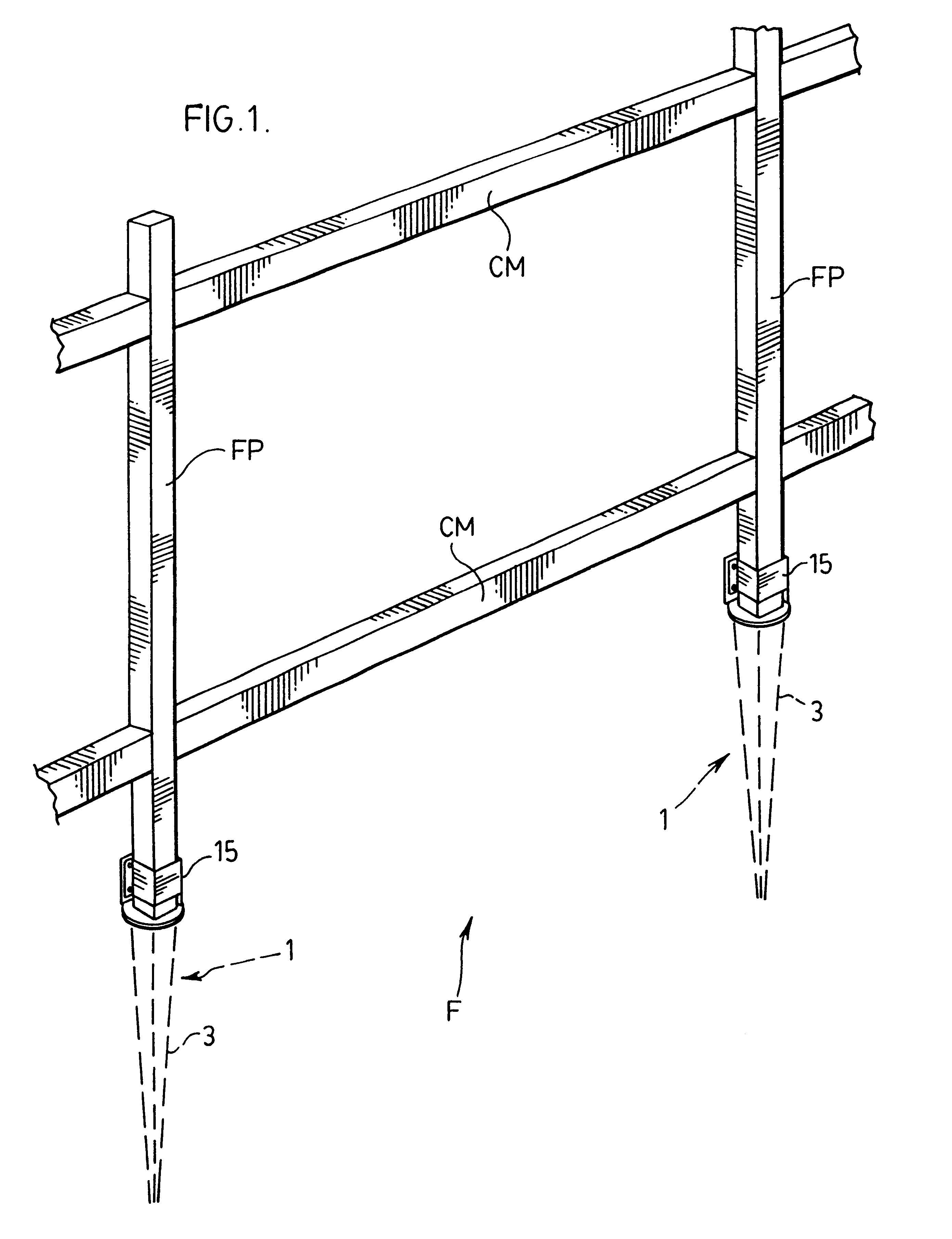
FIG. 1 shows a section of a fence generally indicated at F. This fence is formed by a pair of cross members CM held in position by upright fence posts FP. The fence posts are secured to a ground supporting surface by means of fence post holders generally indicated at 1.

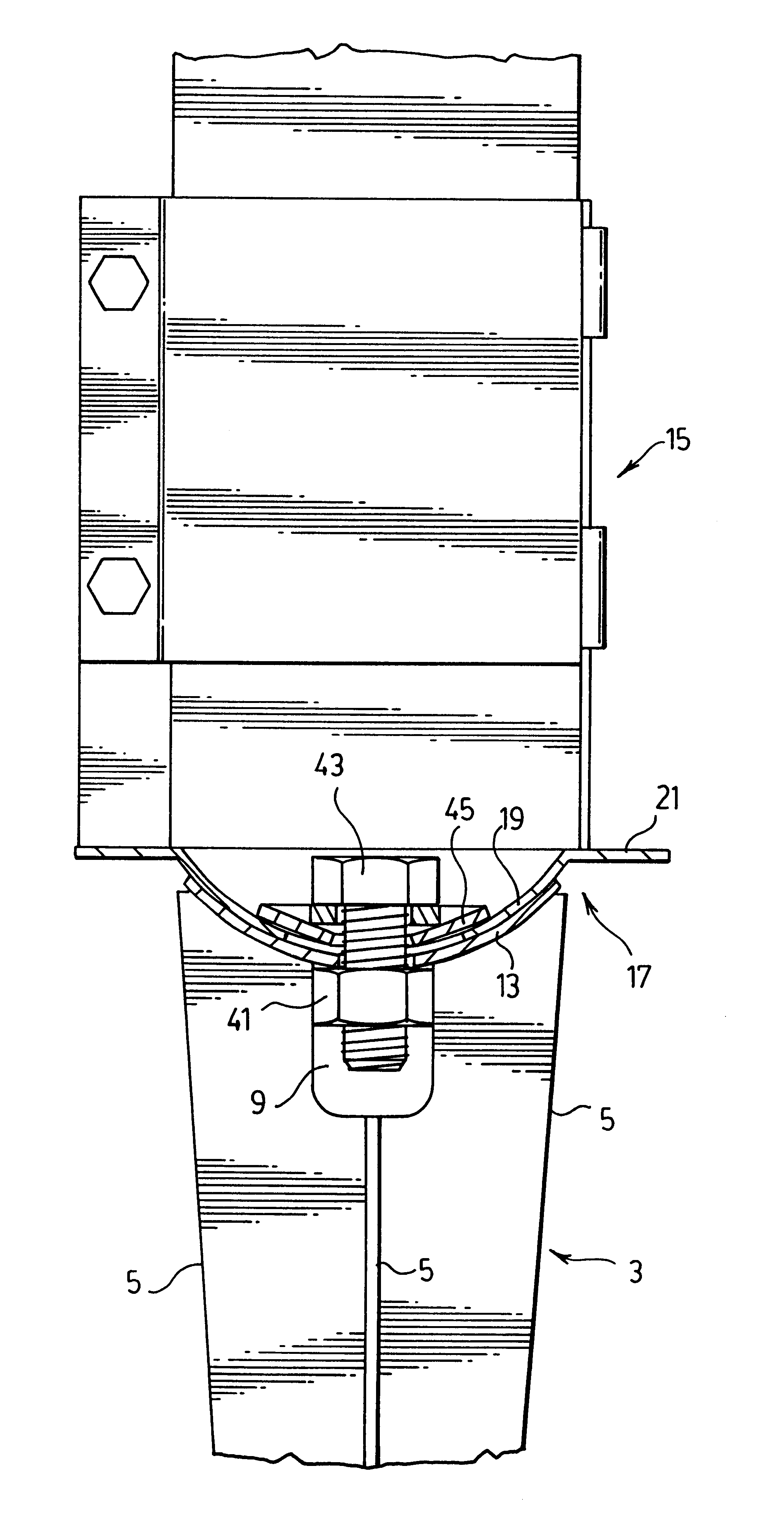
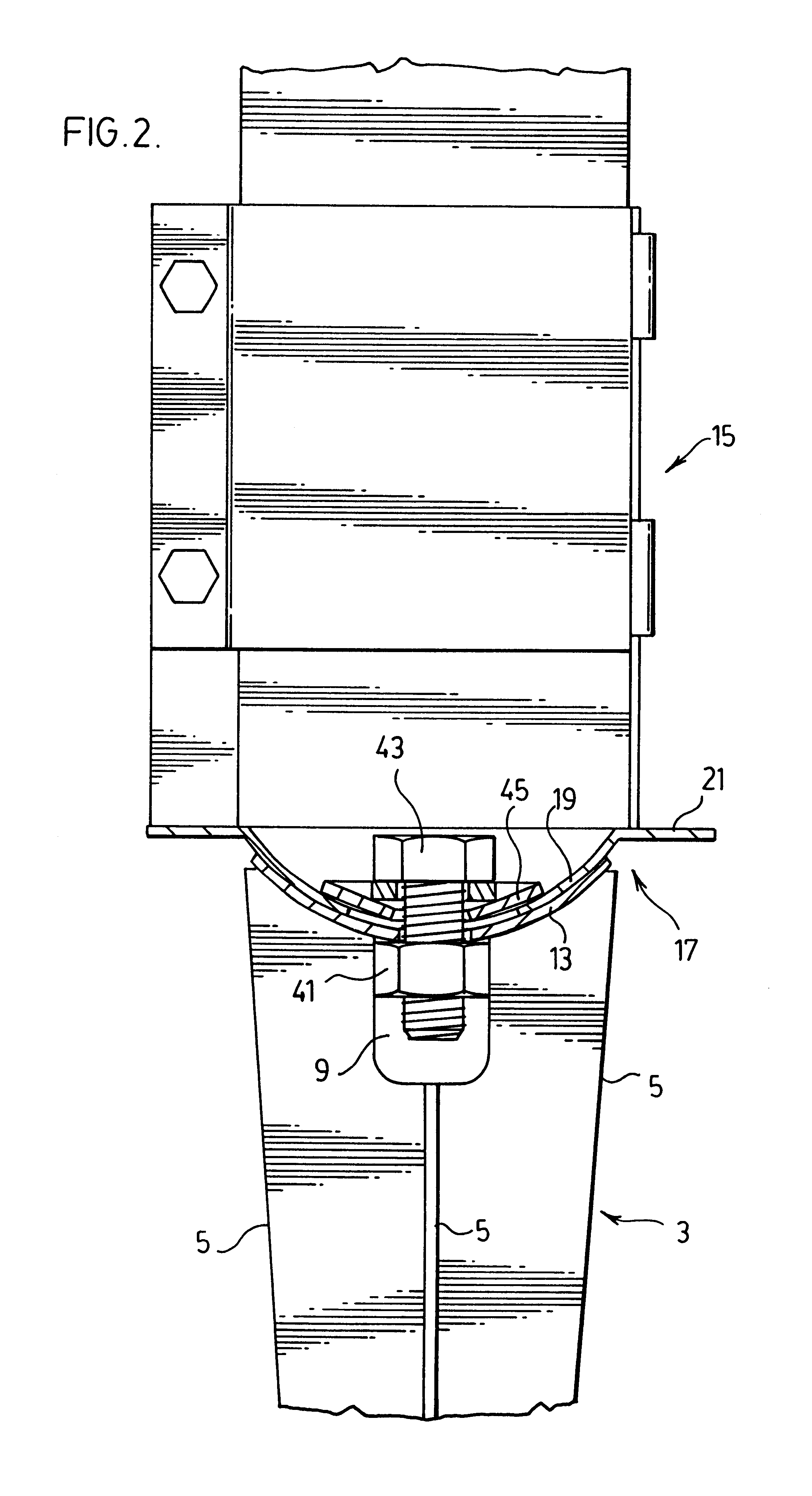
The fence post holders 1, as better shown for example in FIGS. 2 and 7 of the drawings are formed by a lower spike portion generally indicated at 3 and an upper bracket portion generally indicated at 15. Spike portion 3 embeds into the ground as well shown in FIG. 7 and bracket portion 15 sits above ground level for receiving the bottom end of any one of the fence posts FP.

Referring to FIG. 4 of the drawings, the spike portion 3 is formed by a plurality of tines or blades 5 which join centrally of the spike portion as indicated at 6 and diverge outwardly from their central connection.

Each of the blades 5 has a top surface 7 which curves downwardly inwardly towards a central recess generally indicated at 9. A dish 11 i...


PUM


Abstract

A post holder is formed by a lower spike portion and an upper bracket portion. The bracket portion is connected to the spike portion at an adjustable connection formed by a curved seat at the upper end of the spike portion and a curved base at the bottom end of the bracket portion. This adjustable connection enables different aligned positions of the bracket portion with the spike portion and an adjustable tightening member is provided to lock the bracket portion with the spike portion in any one of these different aligned positions.

Description

The present invention relates to a post holder of the type having a ground imbedding spike and a bracket for receiving the base of a post such as a fence post.Until recent years, most fence posts were held in position by first digging a large opening in the ground supporting surface for the fence post, filling the opening with concrete and before the concrete has an opportunity to set locating the bottom end of the fence post in the concrete.The above process is very labor intensive and requires special working tools such as augers and the like for digging the ground out to receive the concrete base for the post.In order to make it easier to embed the base of a fence post or any other type of ground support post, specifically designed post holders have been developed in the relatively recent past. For example, U.S. Pat. No. 4,874,149 shows a fence post holder having a bottom spike which is embedded into a ground supporting surface with a bracket fixed to the top of the spike for rec...

Claims


Application Information

Patent Timeline
Patent Type & Authority Patents(United States)
IPC IPC(8): E04H12/22
CPCE04H12/2284E04H12/2215
Inventor MEYER, GEORGE
Owner ROYAL CAPITAL STAMPING & TOOLING
Why Eureka
Try Eureka