

Image forming apparatus having an injection charging system and a two component contact development device
Inactive Publication Date: 2001-09-25
CANON KK
View PDF12 Cites 15 Cited by
- Summary
- Abstract
- Description
- Claims
- Application Information
AI Technical Summary
Benefits of technology
voltages, are usable with the same advantageous effects.
Referring to FIG. 3, the description will be made as to a charger 3 according to an embodiment of the present invention. The charger 3 comprises a container 34, a sleeve 31 containing a stationary magnet 32, magnetic particles 35 for injection charging, a regulating member 33 for applying the magnetic particles 35 on the sleeve 31, wherein the sleeve 31 is rotated in such a direction that sleeve 31 surface moves in the opposite direction as the movement direction of the photosensitive member 1 as shown by the arrows at the portion where the magnetic particles 35 are in rubbing contact
Problems solved by technology
It has been found that phenomenon similar to the injection charging unintentionally occurs during the development operation using the magnetic carrier having a volume resistivity of approx.
In the forgoing analysis, the reverse developing system is taken, but the problem is not peculiar to the reverse development system, and the same problem also arises with the regular developing system.
1 time-5 times the total period of the applications of the alternating electric fields, since if it is less than 1 time, the time sufficient for the toner to deposit on the photosensitive drum is not provided, and since if it is longer than 5 times, the toner loo
Method used
View moreImage
Smart ImageViewing Examples

Examples
 PUM
 Abstract
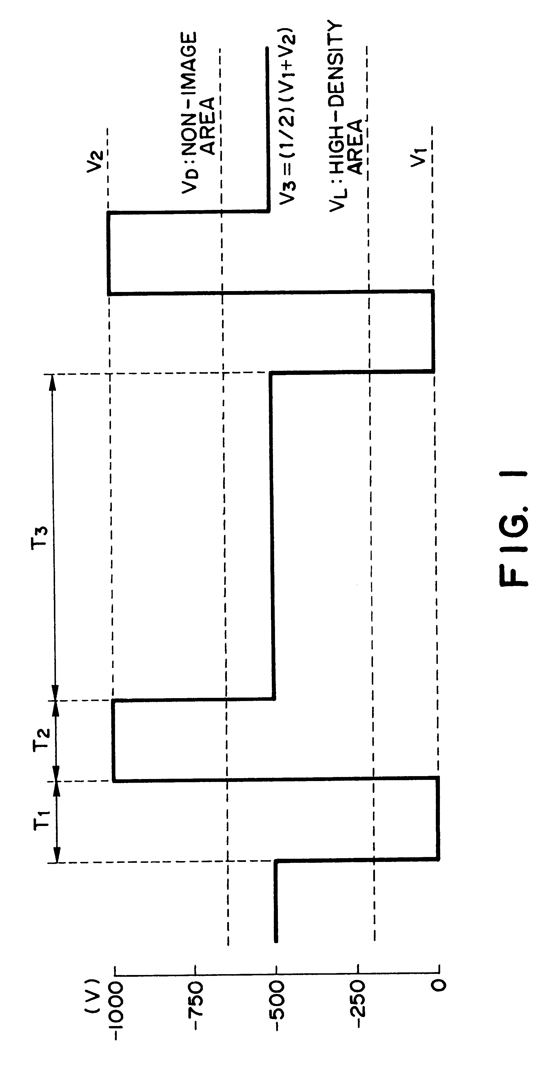
An image forming apparatus includes an image bearing member for carrying an electrostatic image, a contact charger for electrically charging the image bearing member while contacting to a surface of the image bearing member, the contact charger forming an oscillating electric field having a frequency of 100-600 Hz; a developer for developing the electrostatic image on the image bearing member with a developer comprising toner and a carrier having a volume resistivity value of 106-1010 OMEGA.cm, while contacting chains of the carrier to the image bearing member, the developer including a developer carrying member, opposed to the image bearing member, for carrying the developer and electric field forming device for forming an alternating electric filed between the image bearing member and the developer carrying member; wherein the following relationship are satisfied:where T1 is a time duration in which the toner receives force away from the image bearing member toward the developer carrying member; and wherein T2 is a time duration in which the toner receives force away from the developer carrying member toward the image bearing member.
Description
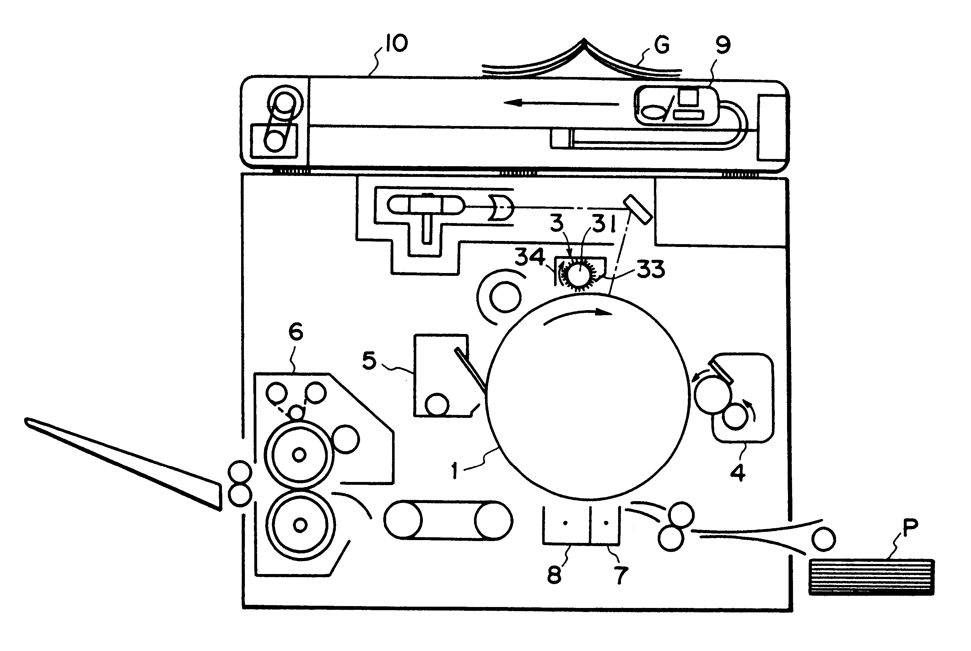
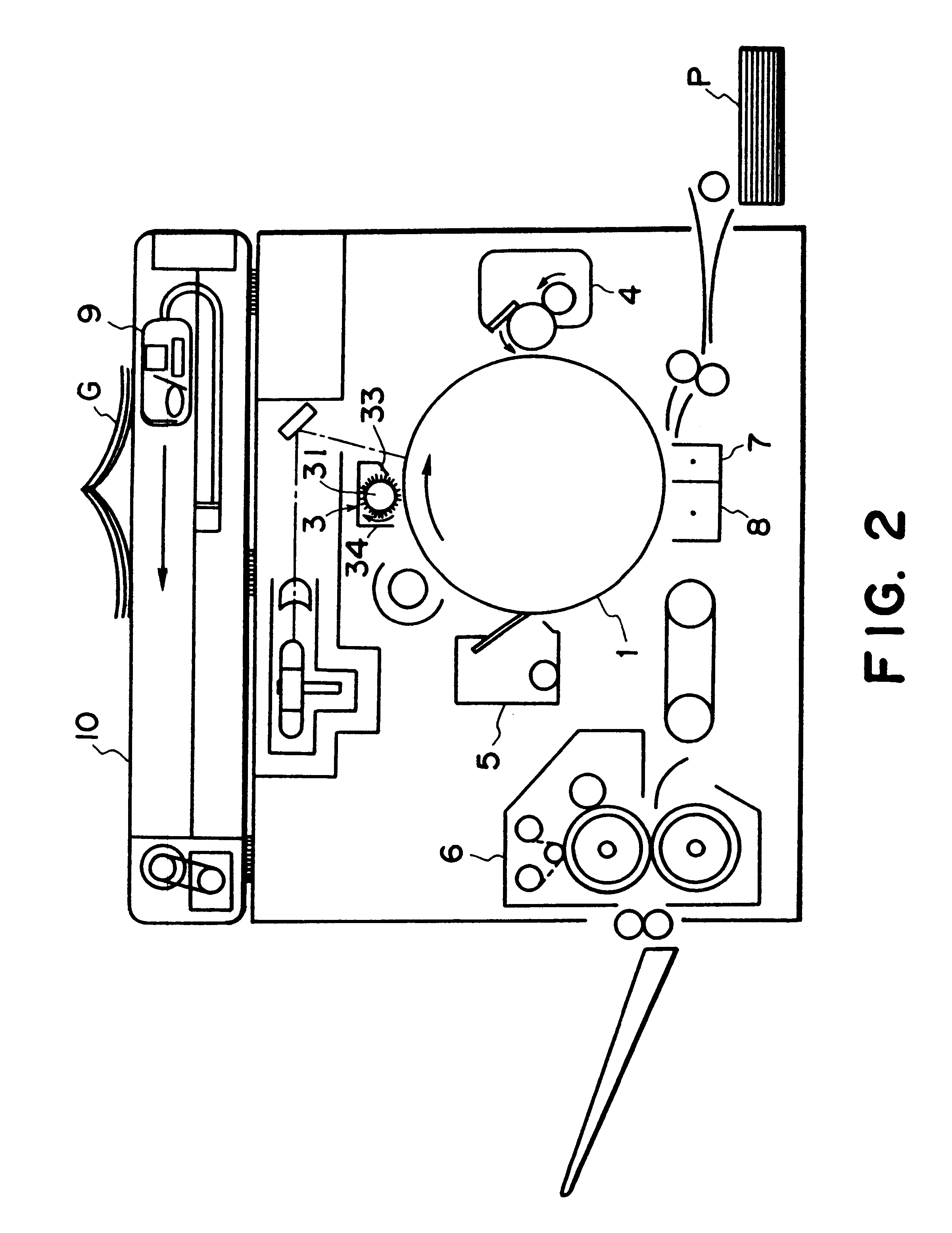
FIELD OF THE INVENTION AND RELATED ARTThe present invention relates to an image forming apparatus such as a copying machine or printer, more particularly to a developing device for developing an electrostatic image on an image bearing member through a two component contact developing method.Referring first to FIG. 6, a conventional image forming apparatus will be described.In this Figure, an original G is placed on an original carriage 10 with the side to be copied facing down. Upon depressing a copy key, the copying operation starts. A unit 9 integrally having a lamp for original projection, a short focus lens array and a CCD sensor, effects a scanning operation while illuminating the original, so that light reflected by the original surface is imaged on a CCD through a short focus lens array.The sensor comprises a light receiving portion, a transfer portion and an output portion, wherein the light receiving CCD portion converts the light signal to a charge signal, the transfer por...
Claims
Login to View More Application Information
Patent Timeline
 IPC IPC(8): G03G15/09G03G15/06G03G15/08
CPCG03G15/065G03G15/0907G03G2215/0609G03G15/09
InventorINOUE, MASAHIROKOBAYASHI, YOSHIAKIWAKI, KENICHIROHIBINO, MASARU
OwnerCANON KK