Conveyor chain link

a conveyor chain and chain link technology, applied in the field of conveyor chains, can solve the problems of adding additional time and effort to the replacement of worn out conveyor chain links, and replacing the entire link

Inactive Publication Date: 2002-02-19
RAMSEY EARL
View PDF16 Cites 61 Cited by
  • Summary
  • Abstract
  • Description
  • Claims
  • Application Information

AI Technical Summary

Problems solved by technology

Often, the chain will carry caustic, abrasive and corrosive materials which after a period of time tend to eat away at the surface of the chain link.
Eventually, notwithstanding the durability of the other elements of the chain link, the entire link must

Method used


Image

  • Conveyor chain link
  • Conveyor chain link
  • Conveyor chain link

Examples


Embodiment Construction

Persons of ordinary skill in the art will realize that the following description of the present invention is illustrative only and not in any way limiting. Other embodiments of the invention will readily suggest themselves to such skilled persons having the benefit of this disclosure.

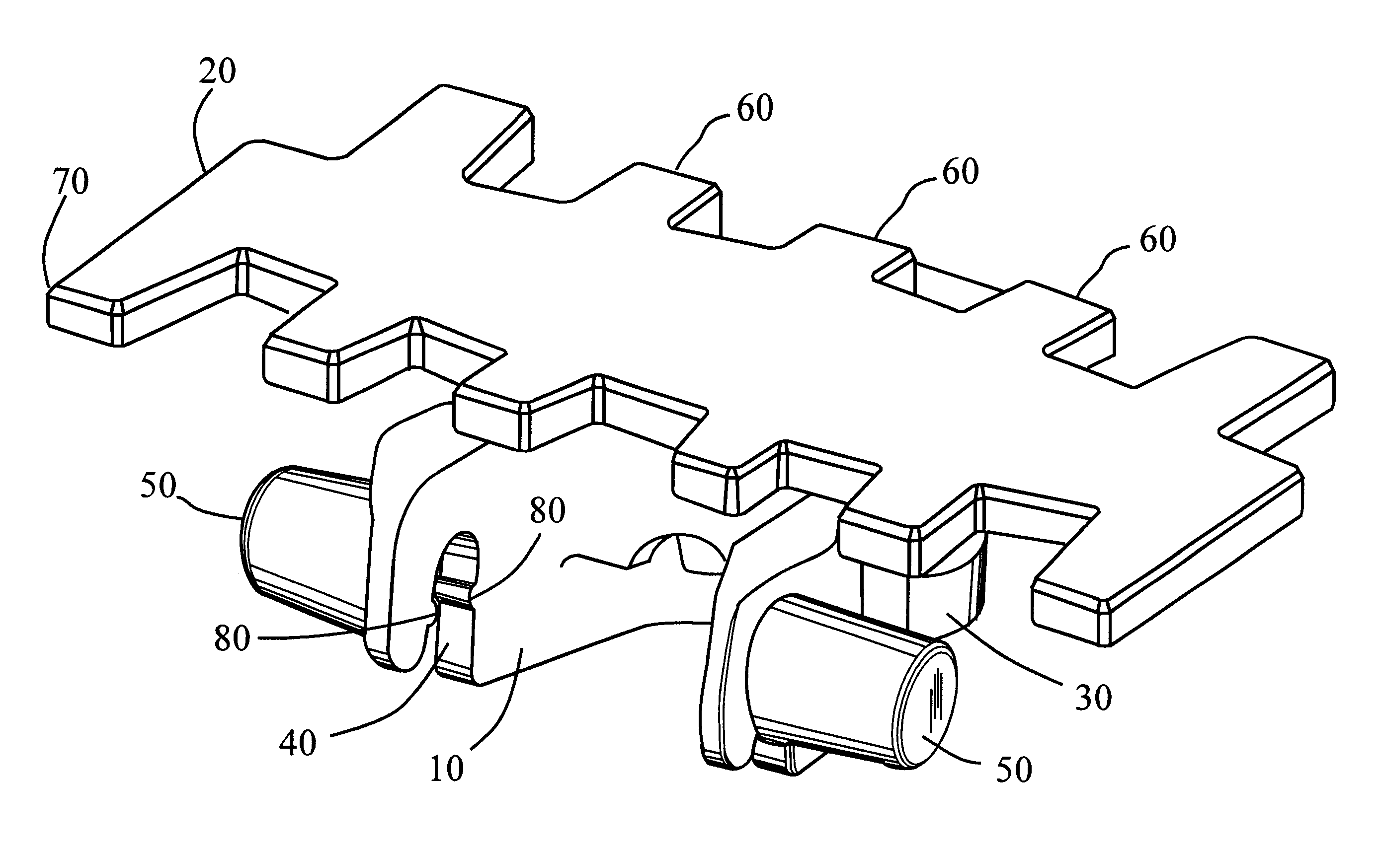
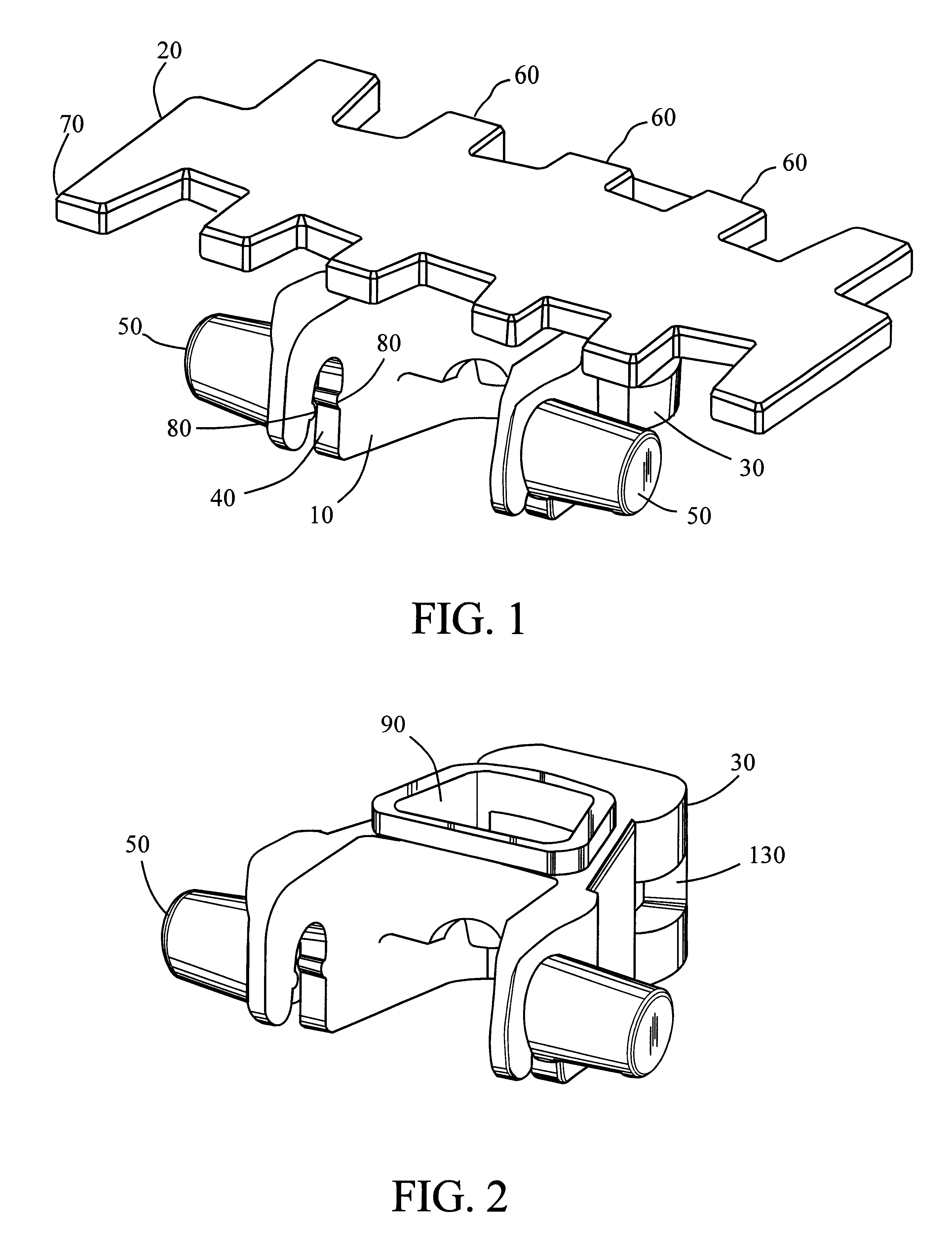
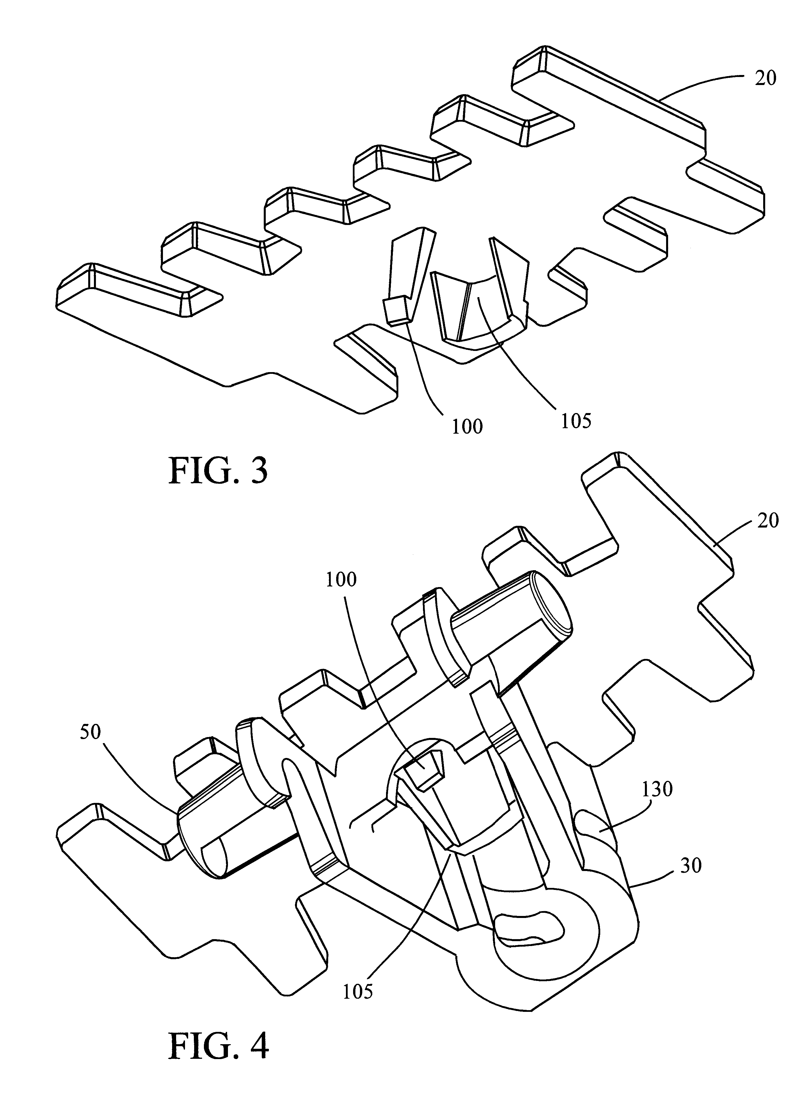
Considering the drawings, wherein like reference numerals denote like part throughout the various drawing figures, reference numeral 10 is directed to the apparatus according to the present invention. The top removable platform portion is denoted by numeral 20. The main body portion is denoted by numeral 30.

Referring to FIGS. 1, 4, 6, 7, 8, 9 and 10, it can be seen that the top removable platform portion 20 may be connected to main body portion 30. Pin opening 40, is shown which can frictionally and easily receive pins to link multiple links together. The main body portion 30 contains trunnions 50, which allow placement of a pin therethrough from the pin opening, 40 underneath. The top platform slat 20 ...


PUM


Abstract

A two piece pivot chain link which through its construction allows the top platform piece to be removably replaceable, additionally the pin attachment means can be frictionally placed in the main body of the pivot chain from the underside allowing for easy placement and removal.

Description

1. Field of the Invention.The present invention relates generally to conveyor chains and more particularly to an improved conveyor chain link.2. The Prior Art.Conveyor chain links are generally well known in the art. In particular applicant refers to U.S. Pat. No. 4,597,492 to Lachonius. et al. Conveyor chains links are linked together in order to provide a continuous chain upon which a variety of objects may be placed to facilitate their movement around, for instance, a factory. The chain construction allows the belt to navigate corners as well as other geometric and spatial problems. Often, the chain will carry caustic, abrasive and corrosive materials which after a period of time tend to eat away at the surface of the chain link. Eventually, notwithstanding the durability of the other elements of the chain link, the entire link must be replaced due to the wear suffered by the platform portion of the chain link. Additionally, links are attached to one another through the use of pi...

Claims


Application Information

Patent Timeline
IPC IPC(8): B65G17/30B65G17/40B65G17/08B65G17/06
CPCB65G17/086B65G17/44B65G17/40B65G2201/02
Inventor RAMSEY, EARL
Owner RAMSEY EARL
Why Eureka
Try Eureka