Adjustable hangar

a technology of adjustable height and hangar, which is applied in the direction of hose connection, machine support, other domestic objects, etc., can solve the problems of inability to adjust or loosen the flexible tie device, the conventional art has several problems, and the conventional art devices cannot be secured to a mounting structur

Inactive Publication Date: 2002-05-07
SIMPSON DENNIS +1
View PDF16 Cites 17 Cited by
  • Summary
  • Abstract
  • Description
  • Claims
  • Application Information

AI Technical Summary

Problems solved by technology

Often, the flexible tie device cannot be adjusted or loosened and must be destroyed (e.g. cut) in order to release the previously bound article.
Several problems exist in the conventional art.
Specifically, conventional art devices cannot be secured to a mounting structure in a variety of orientations and therefore the application of the devices is limited.
In addition, the cost of manufacturing the conventional art devic

Method used


Image

  • Adjustable hangar
  • Adjustable hangar
  • Adjustable hangar

Examples


Embodiment Construction

Reference will now be made in detail to a preferred embodiment of the invention, an example of which is illustrated in the drawings.

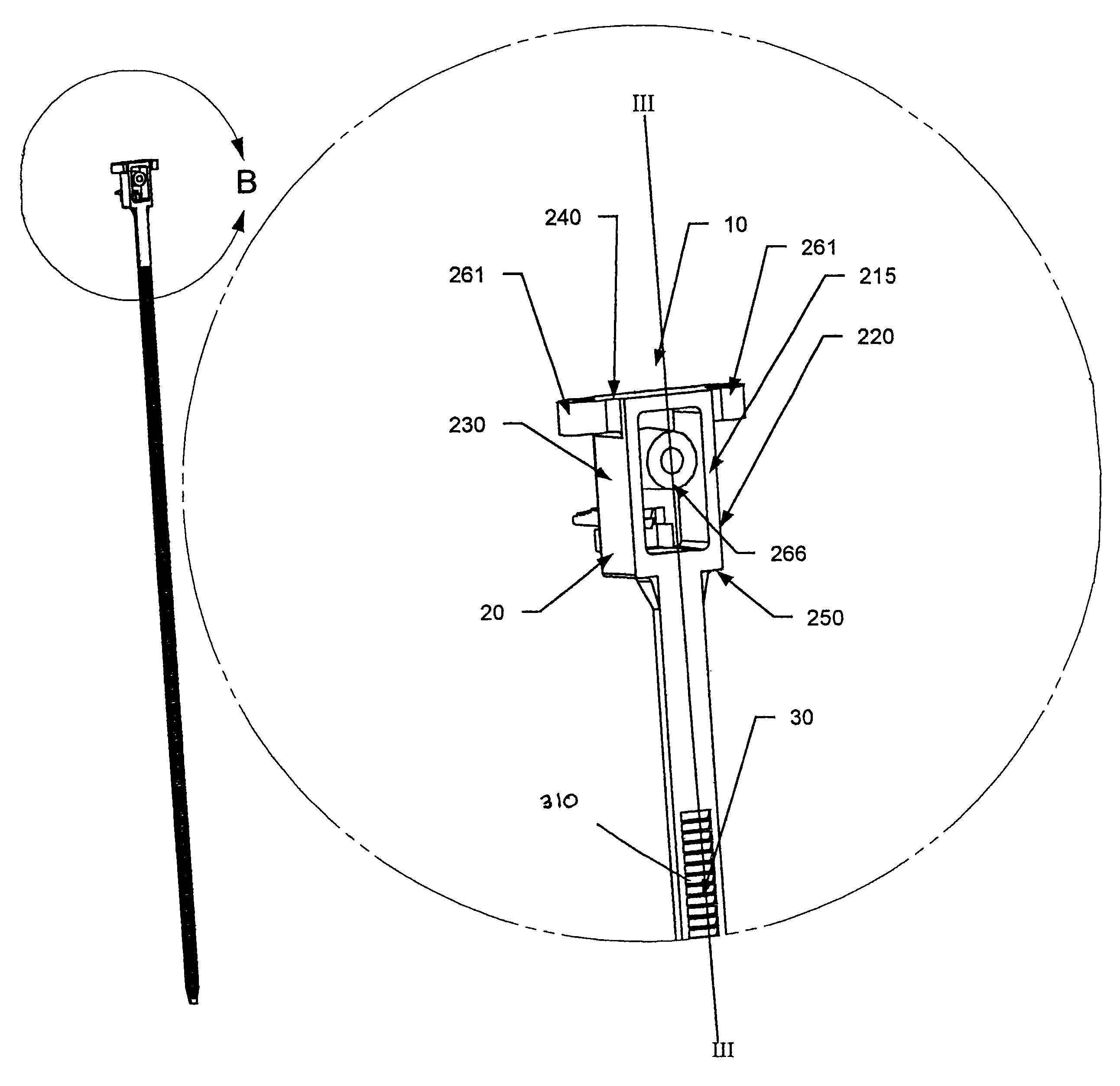
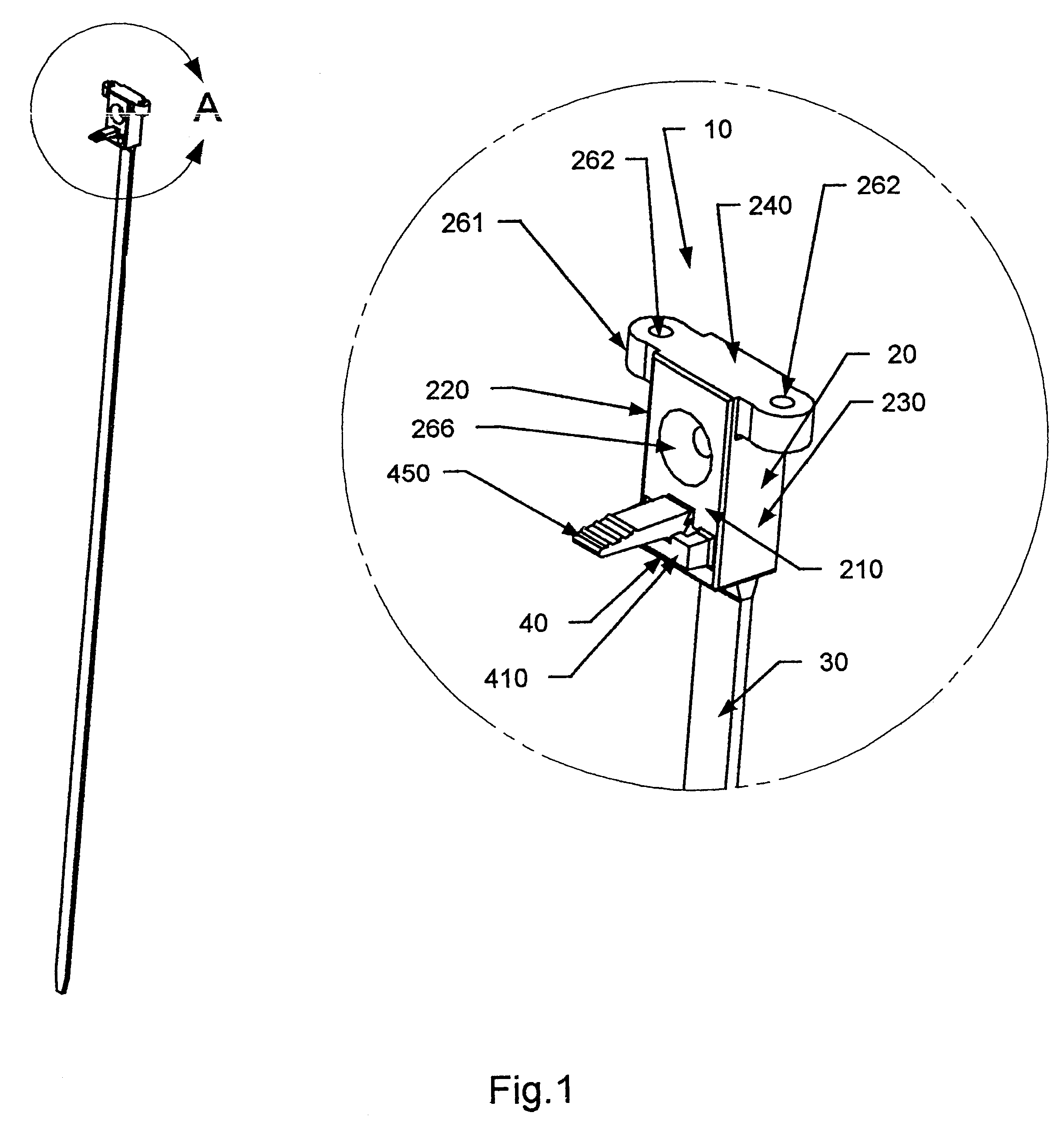
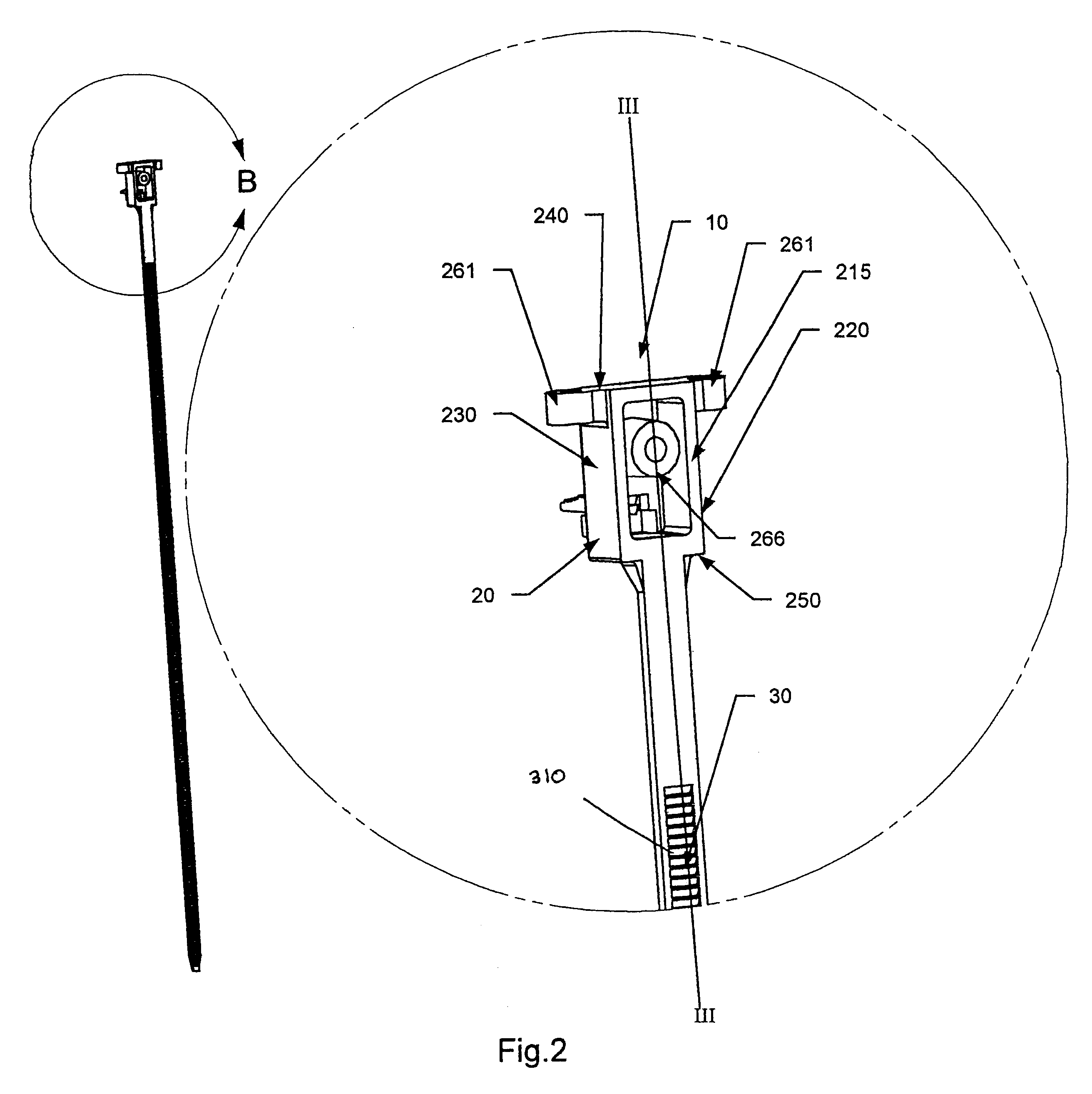
As shown in FIGS. 1 and 2, a pipe hangar device 10 can include a housing 20 and an adjusting strip 30. The pipe hangar device 10 can be disposed on a mount structure 600 through the use of fastener structures 261, 266 located on the housing 20. A pipe or other hanging 15 structure can be adjustably positioned and supported by the pipe hangar device 10 by. looping the adjusting strip back over itself and locking it to the housing 20 using an adjusting lock 450 located on the housing 20. The mounting of the pipe hangar device 10 to the mount structure 600 and the adjustment of the position of the pipe will be described in more detail later.

The housing 20 preferably includes a front face 210, a rear face 215, a left face 220, a right face 230, a top face 240, and a bottom face 250. The left face 220 can be substantially parallel to the right face 230 and t...


PUM


Abstract

A pipe hangar that can be mounted in various orientations for adjustably securing or hanging a structure at different locations can include a housing having an adjusting strip, a locking tab, and multiple and differently oriented fastener structures, e.g., voids. The locking tab can include a strip guide and a lever including a tooth stop. The adjusting strip can include connecting teeth and be disposed on a bottom portion of the housing. The adjusting strip is adapted to be looped back over itself and placed between the strip guide and the housing such that the connecting teeth on the adjusting strip can be engaged by the tooth stop on the lever to lock the adjusting strip relative to the housing. A pipe or other structure disposed in the portion of the adjusting strip that is looped back over itself can be raised or lowered relative to the housing (and the structure to which the housing is mounted) by pressing the lever to release the adjusting strip connecting teeth from the tooth stop, moving the adjusting strip to a desired positioned relative to the housing, and releasing the lever to engage the tooth stop with the connecting teeth and lock the adjusting strip relative to the housing at the desired position.

Description

1. Field of the InventionThe invention relates to a hangar, and more particularly to an adjustable height pipe hangar adapted to be mounted in different orientations for adjustably securing a pipe or other structure at various locations.2. Description of the Related ArtFlexible tie devices for fastening elongated structures, such as cables, pipes and the like, are well known in the art. Such devices usually consist of a one-piece flexible strap element which is wrapped around a set of cables or the like, and then inserted into a socket that is built into one end of the flexible strap. The socket and the flexible strap usually include mating toothed elements which can securely fasten the flexible strap within the socket. Often, the flexible tie device cannot be adjusted or loosened and must be destroyed (e.g. cut) in order to release the previously bound article.As shown in U.S. Pat. No. 4,958,414 to Benoit (Benoit'414), it is known to use an adjustable, reusable fastener device when...

Claims


Application Information

Patent Timeline
IPC IPC(8): F16L3/22F16L3/233
CPCF16L3/2334Y10T24/1498
Inventor SIMPSON, DENNISDOLAN, BUCK
Owner SIMPSON DENNIS
Why Eureka
Try Eureka