Device for the connection of a multiple-tube structure and method of access to this device

a multiple-tube structure and access method technology, applied in the installation of lighting conductors, cables, insulated conductors, etc., can solve the problems of difficult and number, inconvenient work, and encumbrance of cable access chambers

Inactive Publication Date: 2002-07-30
GULA CONSULTING LLC
View PDF18 Cites 36 Cited by
  • Summary
  • Abstract
  • Description
  • Claims
  • Application Information

AI Technical Summary

Problems solved by technology

However, the increase in the stiffness and number of these tubes and the management of the extra lengths causes the cable access chambers to be encumbered.
This does not facilitate work.
However, if

Method used


Image

  • Device for the connection of a multiple-tube structure and method of access to this device
  • Device for the connection of a multiple-tube structure and method of access to this device
  • Device for the connection of a multiple-tube structure and method of access to this device

Examples


Embodiment Construction

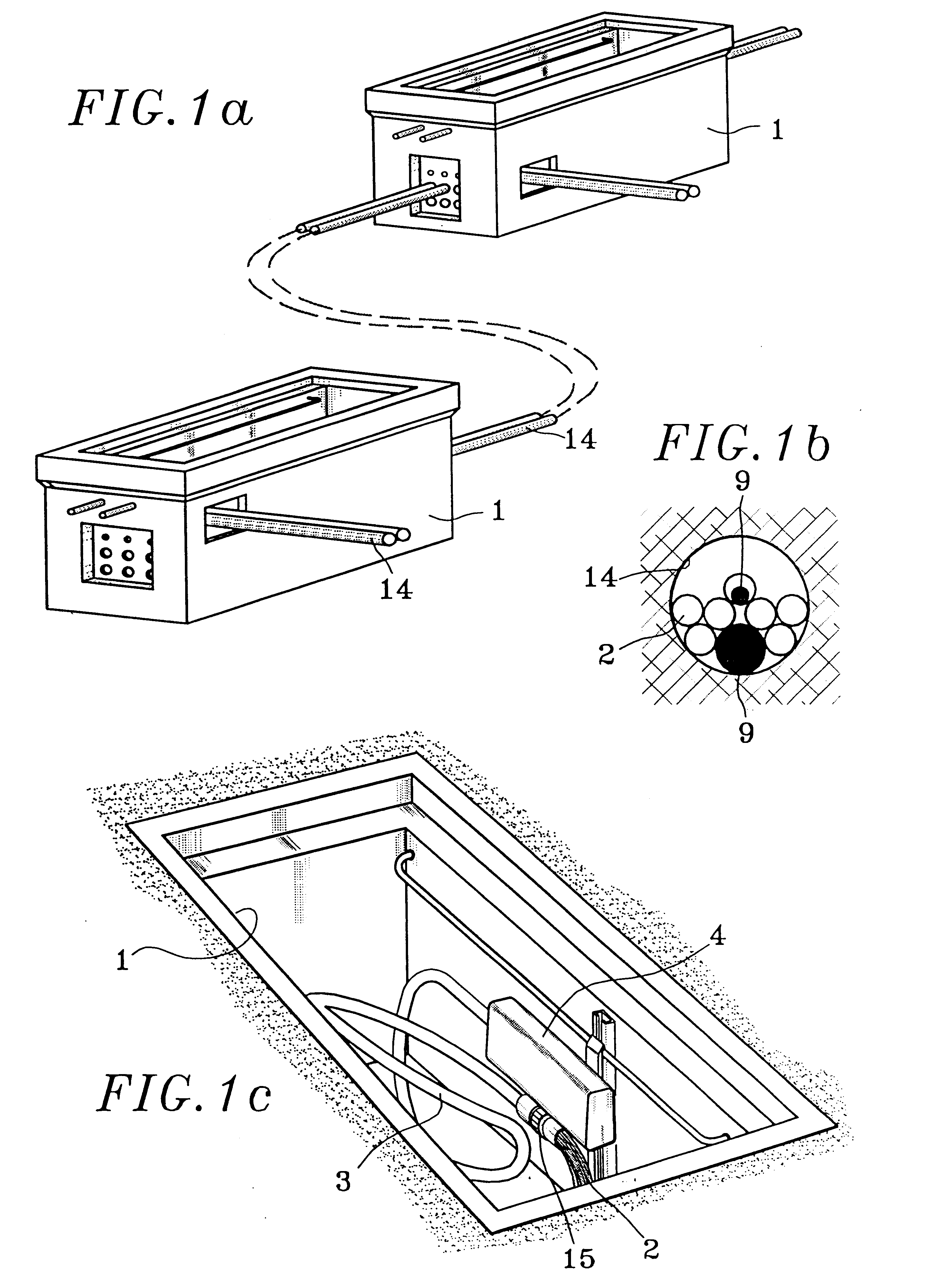
The underground infrastructure shown in FIG. 1a) is made up of cable access chambers 1 connected to one another by ducts 14. These ducts 14 reach the front of a cable access chamber 1 at the level of a mask. The cable access chambers 1 may comprise several masks.

FIG. 1b), which has already been described, provides an exemplary illustration of a duct 14 containing a large cable 9, with tubes 2 protecting smaller cables 9. A duct 14 may also contain minitubes that protect microcables or it may contain only one of these elements.

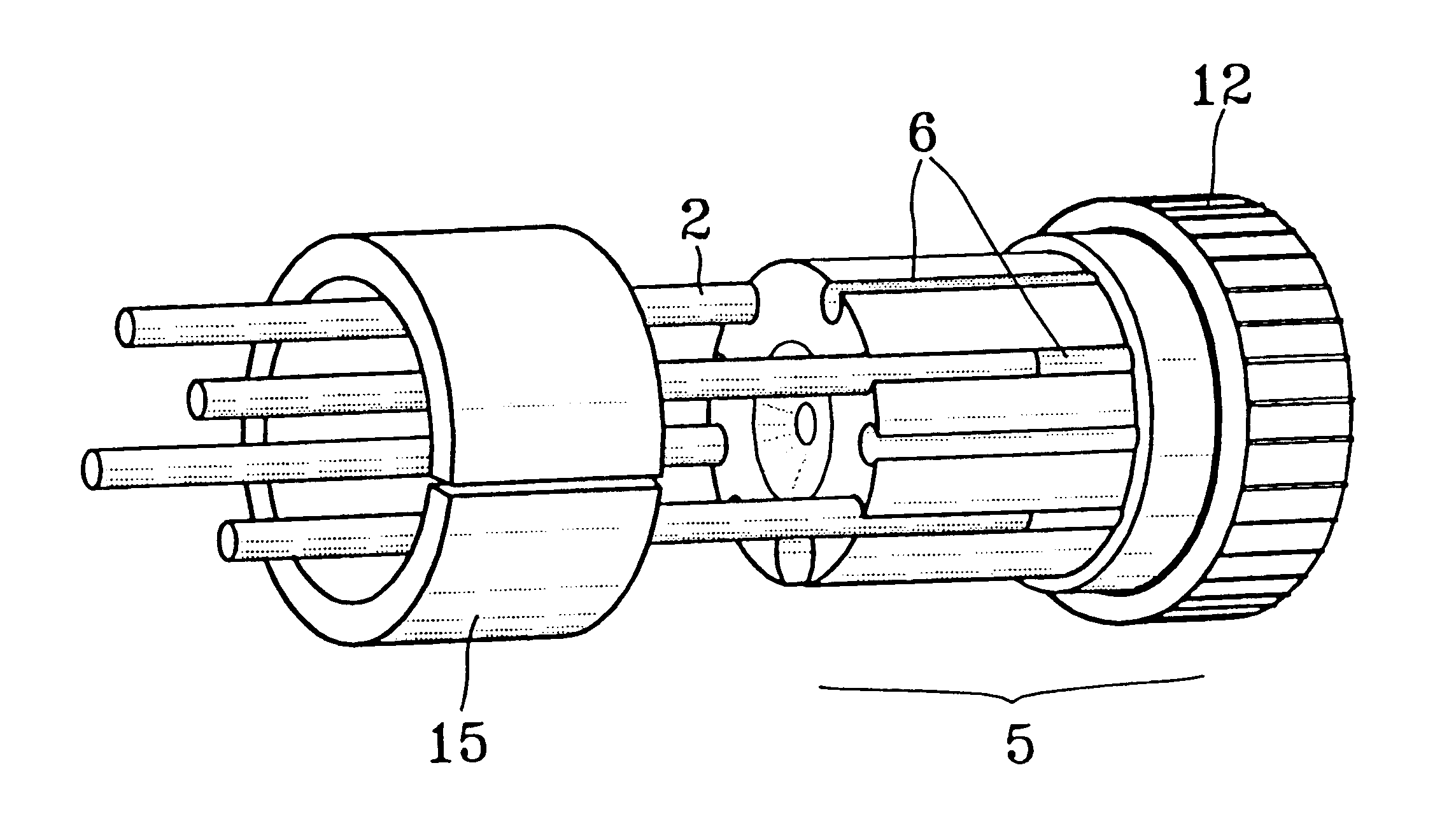
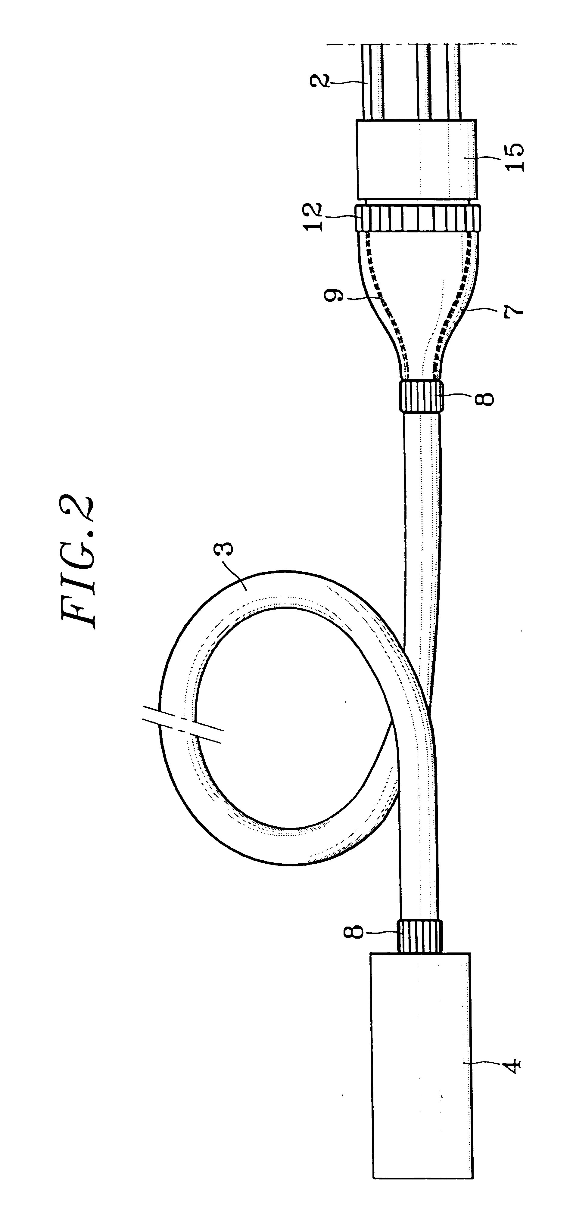
FIG. 1c) shows a cable access chamber 1 in which a flexible sheath 3 provides a connection, to a box 4, for the cables coming from the tubes 2 reaching the cable access chamber 1. The cables are thus assembled at the exit of the tubes 2 and protected throughout their route to the box 4. In this FIG. 1c), the cables are concealed by the tubes 2 or the sheath 3. The flexible sheath 3, into which there pass all or a part of the cables coming from the tubes 2, can ...


PUM


Abstract

A device for connection between the ends of tubes (2) protecting one or more cables (9) and a box (4), has a flexible sheath (3) that makes it possible, at the exit from the tubes (2), to connect the cables (9) coming from the tubes (2) to the box in providing for the protection of the said cables (9) and enabling the moving away of the box (4) to be accessed.

Description

Field of the InventionThe invention relates to a connection device between the ends of tubes and a box from which there emerges a plurality of cables.The field of the invention is that of a wired network for telecommunications, power, lighting or signalling.More particularly, a description shall be given of a wired telecommunications network that itself brings together several types of networks to which there correspond various morphologies of infrastructure. A distinction may be made between;interconnection networks, which connect networks of distinct telecommunications operators. The connections between these networks use underground conduits that are operated jointly.transmission networks belonging to one or more operators and comprising nodes called telecommunications exchanges. The transmissions are sometimes made by means of RF channels but, given the quantity, confidentiality and need to securitize the information to be transmitted, it is often preferred to use cable transmis...

Claims


Application Information

Patent Timeline
IPC IPC(8): G02B6/44H02G9/00H02G9/10H01B17/58H02G1/06
CPCG02B6/4472H02G9/10G02B6/4451G02B6/443G02B6/4446Y10T16/05G02B6/501
Inventor MIGNON, PIERRECRESPEL, DANIELSCHREIBER, YANNICK
Owner GULA CONSULTING LLC
Why Eureka
Try Eureka