Fluid filter

a filter and flue gas technology, applied in the field of flue gas filters, can solve the problems of posing a series of threats to the structural integrity of these kinds of filters, high risk of damage, and high risk of fine meshes or nets used as filters

Inactive Publication Date: 2002-08-27
CHAPIN MFG INC
View PDF23 Cites 108 Cited by
  • Summary
  • Abstract
  • Description
  • Claims
  • Application Information

AI Technical Summary

Problems solved by technology

Fine meshes or nets used as filters are highly susceptible to clogging, and are even more susceptible to damage under conditions of extreme pressure combined with jagged debris caught by the filter.
This renders these types of filters of little use in applications such as garden sprayers or recreational fuel tanks, where typically varied and voluminous amounts of debris get into the sprayers or tanks, thereby posing a series threat to the structural integrity of these kinds on filters.
Such separation of components necessitates undesirable assembly, and presents the possibility of disassembly or disconnection problems under physical stress to the filter.
However, in an attempt to prevent the end of the discharge tube from clogging with debris, neither of the conventional prior art solutions depicted in FIGS. 1a and 1b locates the end of the discharge tube at or very near the bottom of the tank.
By not locating the discharge tube at or very near the bottom of the tank the user is unable to draw any fluid remaining in the bottom of the tank, thereby wastefully and inefficiently leaving fluid behind.

Method used


Image

  • Fluid filter
  • Fluid filter
  • Fluid filter

Examples


Embodiment Construction

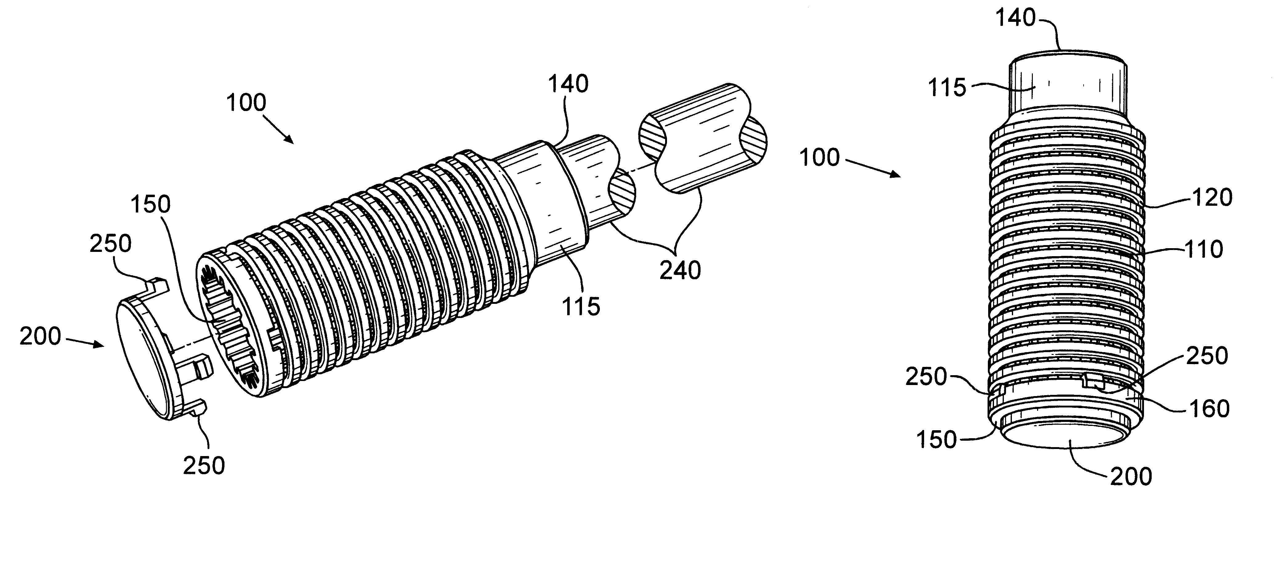
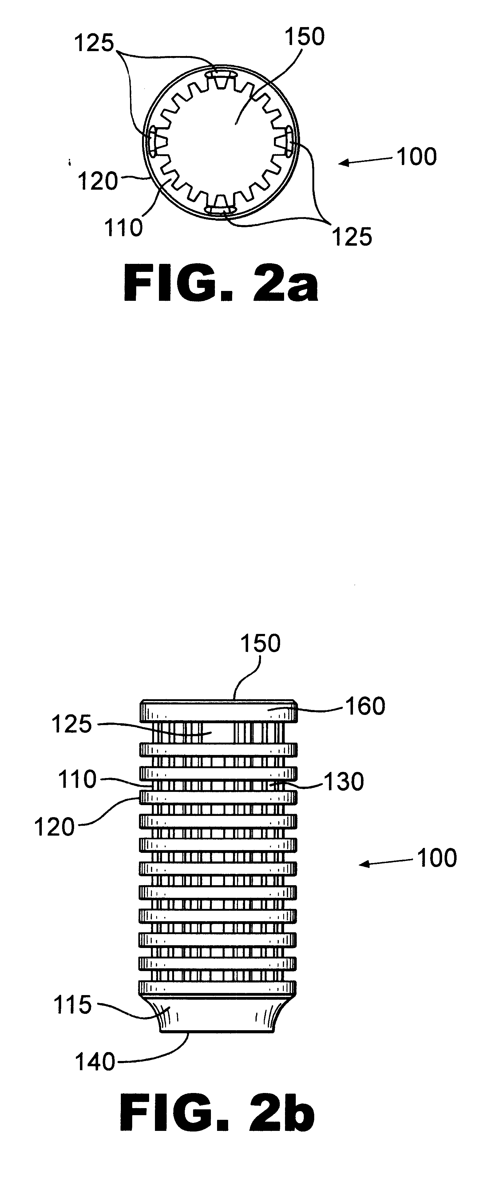
The present invention will be described below with reference to the illustrated embodiments referred to in FIGS. 2a, 2b, 2c, 2d, 2e, 3a, 3b, 3c, 4a, 4b, 5a, 5b, 6a, 6b, 7, 8a and 8b. The invention, as depicted in FIGS. 2a, 2b, 2c, 2d, and 2e combines two separate elements of the prior art, a filter and a filter supporting structure, into a single cylindrical fluid filter 100 that is a self-supporting structure, and substantially clog-resistant. The cylindrical filter 100 is preferably constructed with a first plurality of substantially parallel inner longitudinal undulating ribs 110 encircled by second plurality of substantially parallel outer circular ribs 120 thereby forming a grid-like pattern or filtering surface to establish filter openings or apertures 130. The crossed inner and outer ribs provide the structural support for the filter openings 130 and the filter itself. In a preferred embodiment, the first and second substantially parallel ribs comprise, respectively, plastic ...


PUM

PropertyMeasurementUnit
inner diameteraaaaaaaaaa
angleaaaaaaaaaa
pressureaaaaaaaaaa

Abstract

A substantially clog-resistant self-supporting fluid filter for attachment to a discharge tube or the like, comprising a cylindrically shaped grid open at both ends, having a first plurality of substantially parallel ribs crossed by and fastened to a second plurality of substantially parallel ribs at an angle to the first plurality of ribs.Spaces or apertures formed between each adjacent pair of parallel ribs provides passage for liquids to be filtered there through. A circular shaped stop member or snap-on cap having raised radial spacers or lugs is attached to one end of the filter, and prevents the end of the discharge tube slidably inserted into the filter from hitting the top surface of the snap-on cap. Snap-on cap has clips on the outer diameter of the top surface that securely attach the cap to the filter. The fluid filter further comprises a snap-on nipple insert for sealingly engaging the discharge tube and attaching the discharge tube to the filter. The snap-on nipple insert comprises a base, a ribbed body, a tubular body member, and a substantially cylindrical longitudinal opening along the axis of the insert to permit free flow of liquids and gases through the nipple insert. When the fluid filter is attached to the opening at one end of a discharge tube and placed in a fluid filled tank, the discharge tube can extend to the bottom of the tank to be emptied in order to draw any fluid remaining in the bottom of the tank.

Description

This invention relates to fluid filters, and more specifically to substantially clog-resistant fluid filters for attachment to the end of a suction pipe, discharge tube and the like, located in a fluid containing tank.DISCUSSION OF PRIOR ARTAs is well known, suction pipes, discharge tubes and the like, useful for drawing fluids from tanks are typically provided at the tip thereof with a fine mesh or net used as a filter adapted to prevent impurities, contaminates or other undesirable or undissolved particulate material from being entrained by the fluid being drawn. Such filters heretofore known in the art are mostly of the type having a net or mesh-like filter stretched along an opening in such conduits. Fine meshes or nets used as filters are highly susceptible to clogging, and are even more susceptible to damage under conditions of extreme pressure combined with jagged debris caught by the filter. This renders these types of filters of little use in applications such as garden spr...

Claims


Application Information

Patent Timeline
Patent Type & Authority Patents(United States)
IPC IPC(8): B01D29/15B01D29/13B01D35/00B01D35/027
CPCB01D29/15B01D29/46B01D35/027B01D2201/305B01D2201/4084B01D2201/0415Y10T137/2829
Inventor SPRIEGEL, CLARK F.
Owner CHAPIN MFG INC
Why Eureka
Try Eureka