Interchangeable ring

a technology of interchangeable rings and rings, applied in the field of finger rings, can solve the problems of poor retention reliability, unusable and/or unduly complicated retention mechanisms,

Inactive Publication Date: 2002-12-10
GOLDMAN KOLBER
View PDF4 Cites 52 Cited by
  • Summary
  • Abstract
  • Description
  • Claims
  • Application Information

AI Technical Summary

Problems solved by technology

These suffer from various drawbacks, including unsightly and/or undu

Method used


Image

  • Interchangeable ring
  • Interchangeable ring
  • Interchangeable ring

Examples


Embodiment Construction

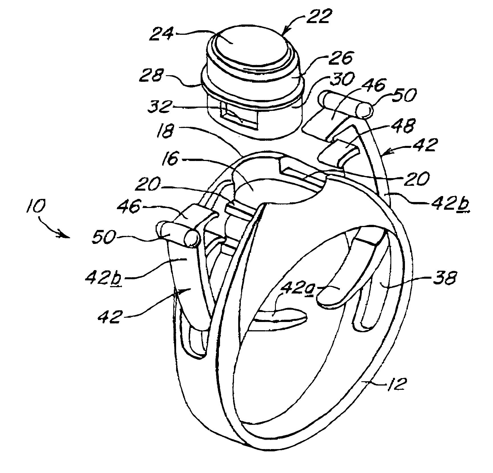
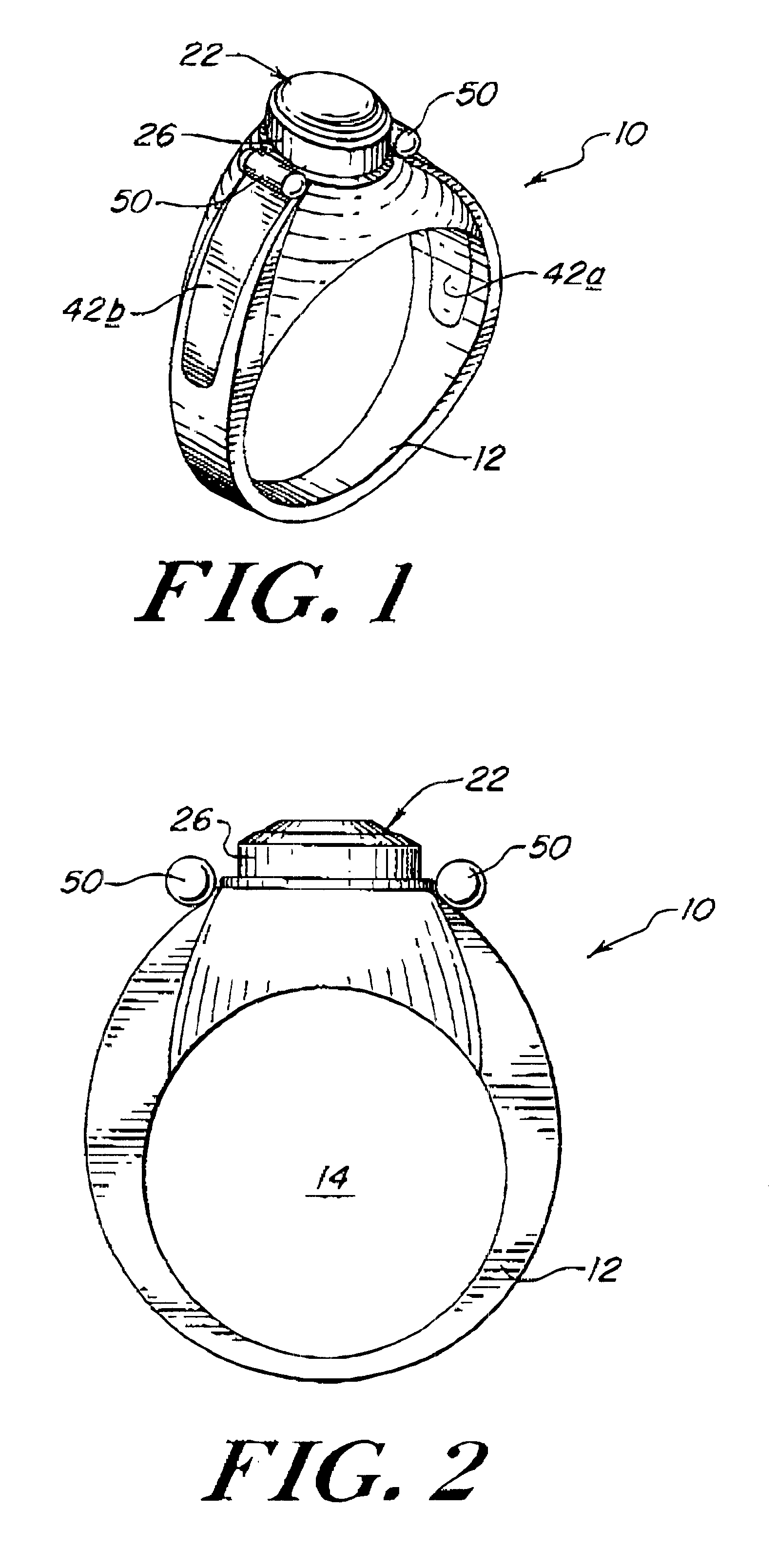
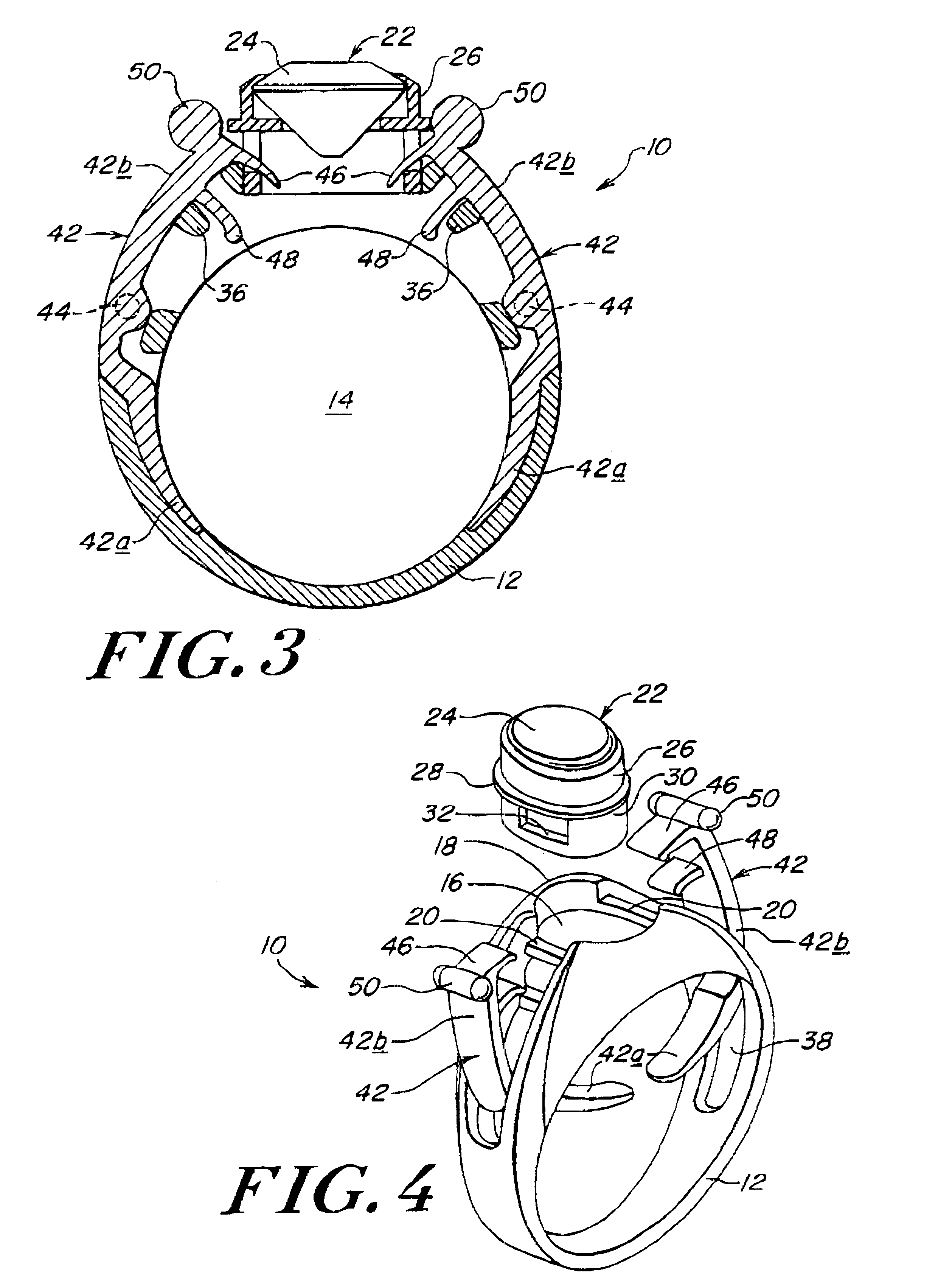
A finger ring in accordance with the present invention is generally depicted at 10 as comprising a generally circular band 12 defining a finger receiving opening 14. The band 12 is provided with a radially outwardly open window 16 surrounded by a first ledge 18 recessed as at 20. A jewelry piece 22 is configured and dimensioned to be received in a displayed position within the window 16. The jewelry piece may include a precious or semiprecious stone 24 or the like set within a metal bezel 26 having a peripheral rim 28 adapted to be seated on the first ledge 18 when the jewelry piece is in its displayed position within the window 16. The jewelry piece is additionally provided with a skirt 30 depending beneath the rim 28. Oppositely disposed first openings 32 are provided in the skirt 30.

The band 12 is further provided with second openings 34 underlying the first ledge 18 on opposite sides of the window 16. The second openings 34 are partially bordered by inwardly projecting second le...


PUM


Abstract

A finger ring comprising a generally circular band defining a finger receiving opening. The band has a radially outwardly open window. A jewelry piece is removably received in a displayed position within the window. A pair of levers is rotatably supported on the band on opposite sides of the window. The levers have inner and outer segments and are rotatably adjustable between open and closed positions. In the open position the inner segments protrude into the finger receiving opening and the outer segments are removed from the window to thereby accommodate insertion and removal of the jewelry piece into and from the displayed position. In the closed positions the inner segments are removed from the finger receiving opening and the outer segments extend into the window to mechanically engage and retain the jewelry piece in the displayed position.

Description

1. Field of the InventionThis invention relates generally to articles of jewelry, and is concerned in particular with a finger ring having interchangeable jewelry pieces.2. Description of the Prior ArtFinger rings having detachable or interchangeable jewelry pieces are known, as shown for example by U.S. Pat. No. 1,182,534 (Driggott); U.S. Pat. No. 1,971,265 (King); U.S. Pat. No. 3,307,375 (Estrin et al.); U.S. Pat. No. 4,794,766 (Schunk et al.); and U.S. Pat. No. 5,996,374 (Bardisbanyan). These suffer from various drawbacks, including unsightly and / or unduly complicated retaining mechanisms, poor retention reliability, etc.A major objective of the present invention is the provision of a finger ring with a simple yet reliable mechanism for securely retaining interchangeable jewelry pieces in place in displayed positions on the ring band.A companion objective of the present invention is the provision of an improved retaining mechanism which does not detract from the overall appearanc...

Claims


Application Information

Patent Timeline
IPC IPC(8): A44C17/00A44C17/02A44C9/00
CPCA44C9/00A44C17/0208
Inventor STEINHAUER, DAVIDSANDOVAL, BYRON
Owner GOLDMAN KOLBER
Why Eureka
Try Eureka