Machine for printing or otherwise decorating hollow bodies

a hollow body and printing technology, applied in printing, rotary presses, transportation and packaging, etc., can solve the problems of reduced mechanical control and guidance accuracy, heavy bending moments, and relative high wear rate of the means provided for orbit correction of the capstan unit, so as to achieve less prone to wear

Inactive Publication Date: 2002-12-10
HINTERKOPF
View PDF17 Cites 10 Cited by
  • Summary
  • Abstract
  • Description
  • Claims
  • Application Information

AI Technical Summary

Benefits of technology

One object of the invention is to create a machine of the type initially mentioned in the case of which the components partaking in orbit correction are less prone to wear.
The correction of the second orbit on motion through the decoration zone is now caused because the pivot shaft is turned through a certain angle, the torque or moment exerted being dependent on the distance between the longitudinal axis of the pivot shaft and the cam following means engaging same. The rotary movement of the pivot shaft leads to a pivotal movement of the pivot point of the pitman means so that the latter, dependent on the direction of rotation, is drawn inward or thrust outward in order to shift the associated capstan unit and to maintain the follow-up movement. In addition to the high precision thus achieved of the orbit correction there is simultaneously an effect such that the forces applied during the decoration operation do not act directly on the cam following means and the cam associated with same, but at least for a major extent are taken up by the pivot shaft and its bearing means. To the extent that a moment is exerted by the decoration forces by way of the pitman means on the pivot shaft, it is possible, by suitable matching of the working lever arms, to ensure that the resulting forces, thrusting the cam following means against the cam, are at a low level. All in all it is accordingly possible for the wear occurring on moving parts to be substantially reduced, something rendering possible high quality performance decoration even after a long working life.
It is convenient for each capstan unit to possess an associated capstan plate bearing the associated receiving capstan by way of which the unit is rotatably supported on the capstan plate. In this case the receiving capstans may be mounted for rotation on the associated capstan plate, something which during the application of decoration allows rotation about the respective axis and accordingly free rotary movement of the hollow bodies on the capstan even if there is substantial friction between such bodies and the receiving capstans. Preferably, in this case each receiving capstan is provided with rotary drive means, with which during the decoration operation enables rotary movement to be caused, something which for example renders possible an extremely accurate development of the printed image during a printing operation.
An other preferred feature of the invention is such that the bearing and guiding measures provided for rendering possible the follow-up movement of the capstan units are provided generally at the same level as the longitudinal axis of the respective receiving capstan, it being possible for each capstan unit to be secured in the direction of rotation of the capstan plate by means of support means secured to the capstan plate. Since in this case the guidance means are practically at the same level as the point of application of the decorating forces, an extremely accurate guidance is possible while substantially eliminating tilting forces. Furthermore, such measures effectively suppress vibrations.
A particularly compact design and with a small mass to be moved is produced if the offsetting part is in each case in the form of a hollow shaft which at least partially surrounds the pivot shaft.

Problems solved by technology

One problem occurring with the known machines of the type initially mentioned resides in the relatively high wear rate of the means provided for orbit correction of the capstan units.
Furthermore, heavy bending moments act on the guide rails of the capstan support.
All in all this means that the accuracy of mechanical control and guidance is reduced with time and accordingly the quality of the decoration operation suffers therewith.

Method used


Image

  • Machine for printing or otherwise decorating hollow bodies
  • Machine for printing or otherwise decorating hollow bodies
  • Machine for printing or otherwise decorating hollow bodies

Examples


Embodiment Construction

The following description of the working example is based on a structure typical for a printing press or machine, the measures relevant for the invention being applicable to other machines for applying decoration as mentioned, as for instance machine for lacquering, labeling, embossing foil or screen printing.

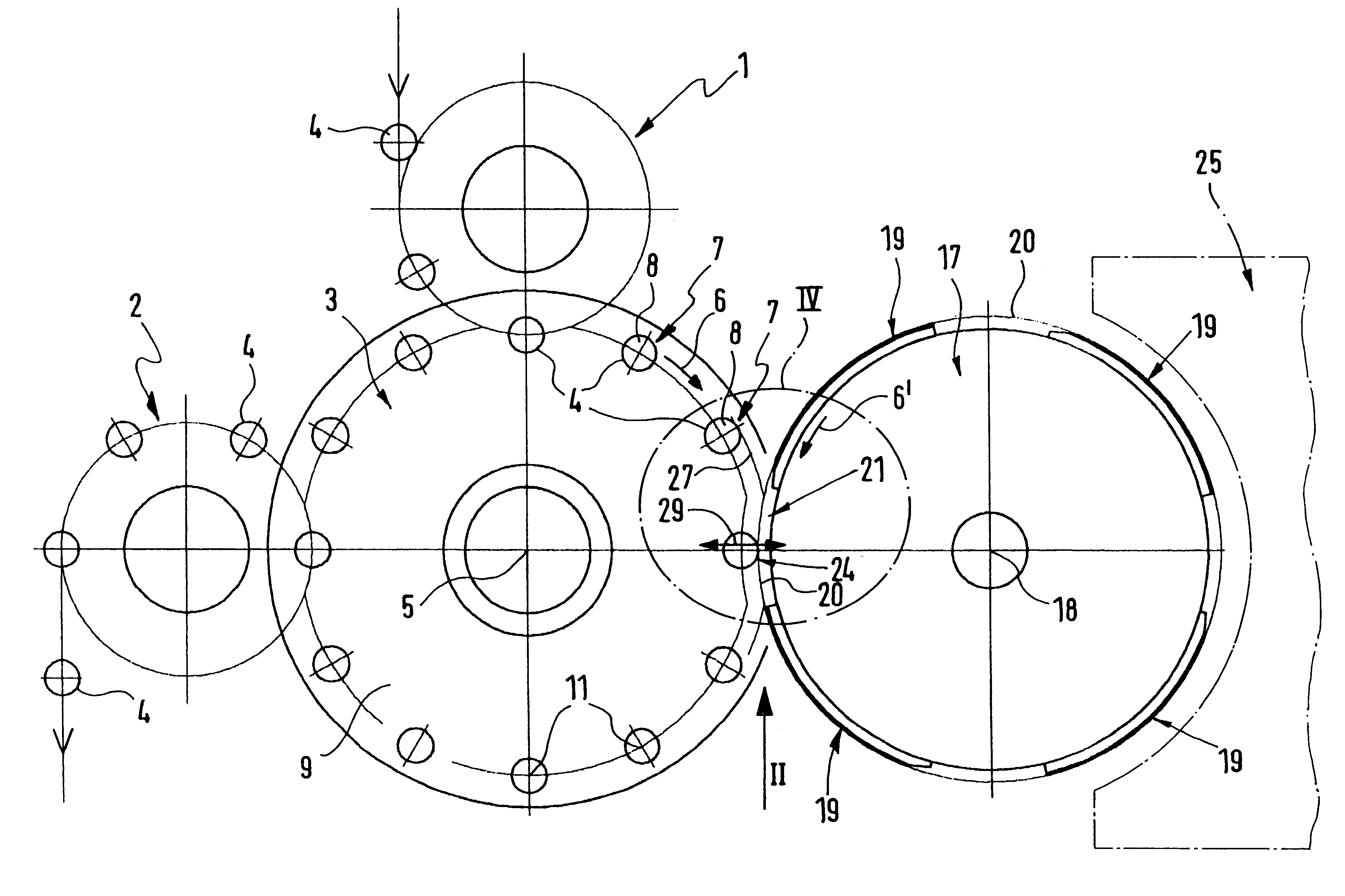
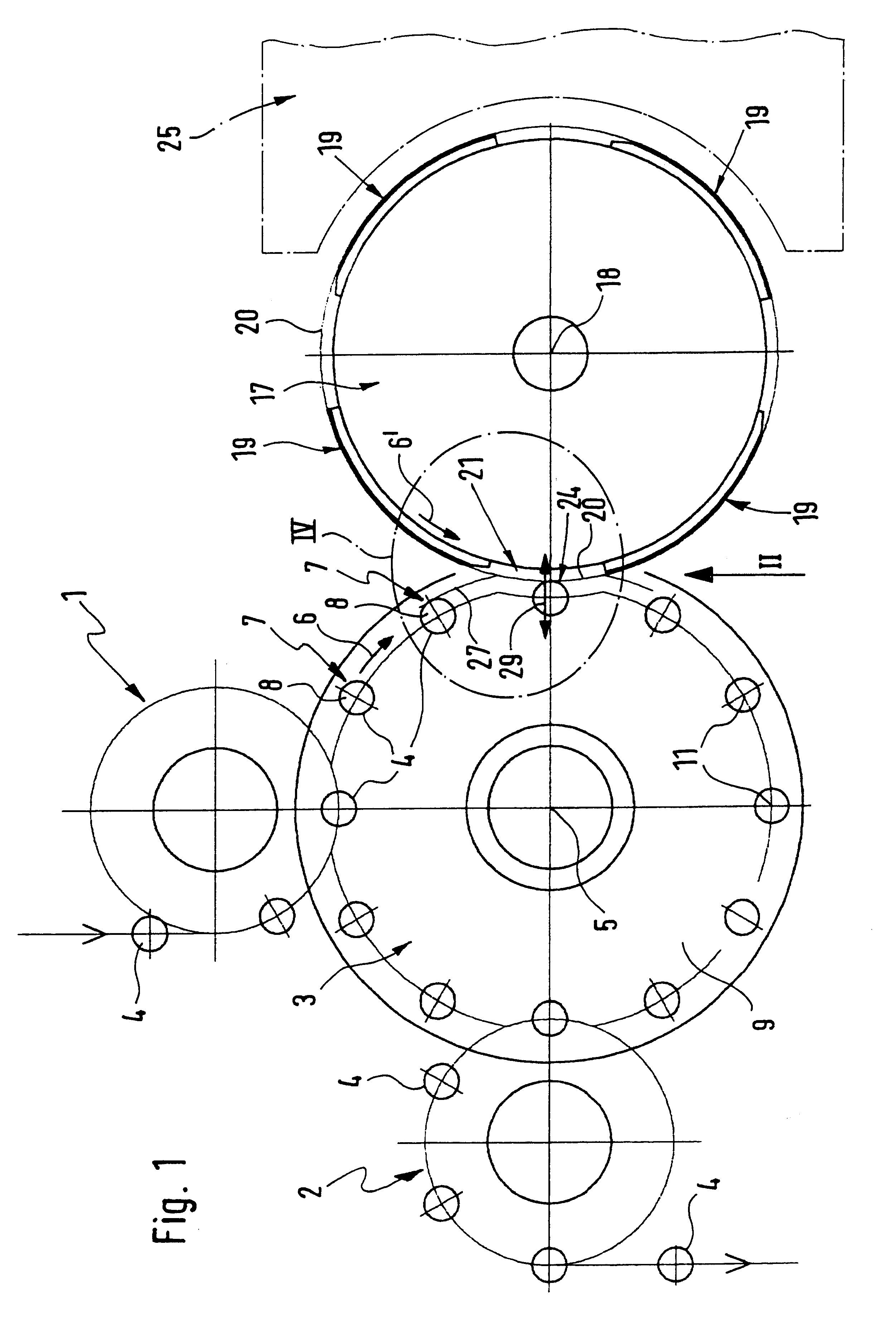
FIG. 1 is fragmentary view of a printing press, which comprises a supply conveying means 1 and a removal conveying means 2, which are associated with the peripheral region of a rotationally driven capstan plate 3. Using the supply conveying means 1 it is possible to supply hollow bodies 4, which are to be printed on, to the capstan plate 3. Using the removal conveying means 2 hollow bodies 4 are taken over by the capstan plate 3, which have already been printed on, and cleared from the machine.

During operation the capstan plate 3 is able to be driven to perform a rotational movement about an axis 5 of rotation as indicated by the arrow, in the direction 6 of rotation. It is fit...


PUM

PropertyMeasurementUnit
distanceaaaaaaaaaa
radial displacementaaaaaaaaaa
radial distanceaaaaaaaaaa

Abstract

A machine for printing on or otherwise decorating hollow bodies. It comprises a rotationally driven decoration application drum, which peripherally is provided with decoration faces, which are able to be moved along a first orbit. On an adjacent capstan plate receiving capstans are arranged for capstan units for carrying hollow bodies. On rotation of the capstan plate the radially inwardly facing sections of the hollow bodies proceed along a second orbit. Pitman units serve to so correct the second orbit on passage through a decoration zone that it coincides with the first orbit.

Description

The invention relates to a machine for printing or otherwise decorating hollow bodies such as sleeves, collapsible tubes, cans or the like comprisinga rotationally driven decoration application drum, which is peripherally provided with one or more decoration applying faces, which on rotation of the decoration application drum proceed along a first circular orbit,a rotationally driven capstan plate whose axis of rotation is arranged athwart that of the decoration application drum, said capstan plate bearing capstan units arranged in sequence at a distance apart in its direction of rotation, said units being respectively provided with a receiving capstan, onto which capstan a hollow body to be decorated may be respectively slipped, the radially outwardly directed sections of the slipped on hollow body proceeding along a second orbit on rotation of the capstan plate,and orbit correction means, which ensure that during a passage, occurring with a simultaneous decoration operation, of a ...

Claims


Application Information

Patent Timeline
Patent Type & Authority Patents(United States)
IPC IPC(8): B41F17/08B41F17/22C09K23/14
CPCB41F17/22
Inventor AICHELE, HELMUT
Owner HINTERKOPF
Why Eureka
Try Eureka