Multi-purpose hanger apparatus for use with a building structure

a technology for building structures and hangers, applied in mechanical devices, other domestic objects, machine supports, etc., can solve the problems of inability to utilize devices to hang structural members of any type from hangers, and the use of such devices is limited

Inactive Publication Date: 2002-12-17
ROTH STEVEN A
View PDF7 Cites 78 Cited by
  • Summary
  • Abstract
  • Description
  • Claims
  • Application Information

AI Technical Summary

Benefits of technology

FIG. 1C is a perspective view illustrating segments of the prior art hanger apparatus of FIG. 1A secured together as a unit along a line of weakness or separation;
FIG. 1D is a view similar to FIG. 1C showing an alternative prior art hanger apparatus wherein the segments are secured together along a line of weakness;
FIG. 2A is a perspective view of another conventional hanger utilized to support a conduit from a hanger rod;

Problems solved by technology

Use of such devices is limited to the particular application for which it is designed.
The devices cannot be utilized to hang a structural member of any type from a hanger rod.

Method used


Image

  • Multi-purpose hanger apparatus for use with a building structure
  • Multi-purpose hanger apparatus for use with a building structure
  • Multi-purpose hanger apparatus for use with a building structure

Examples


Embodiment Construction

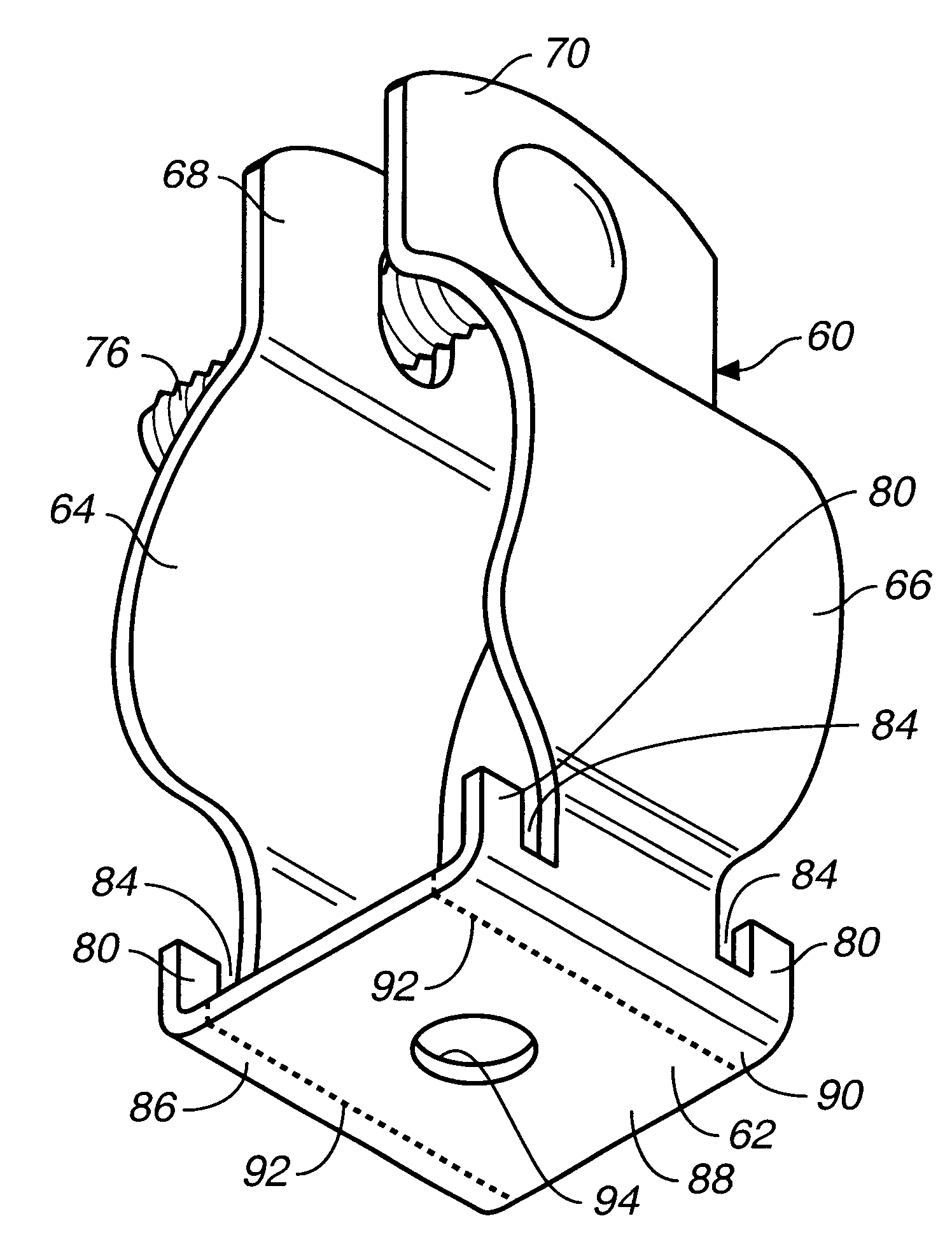
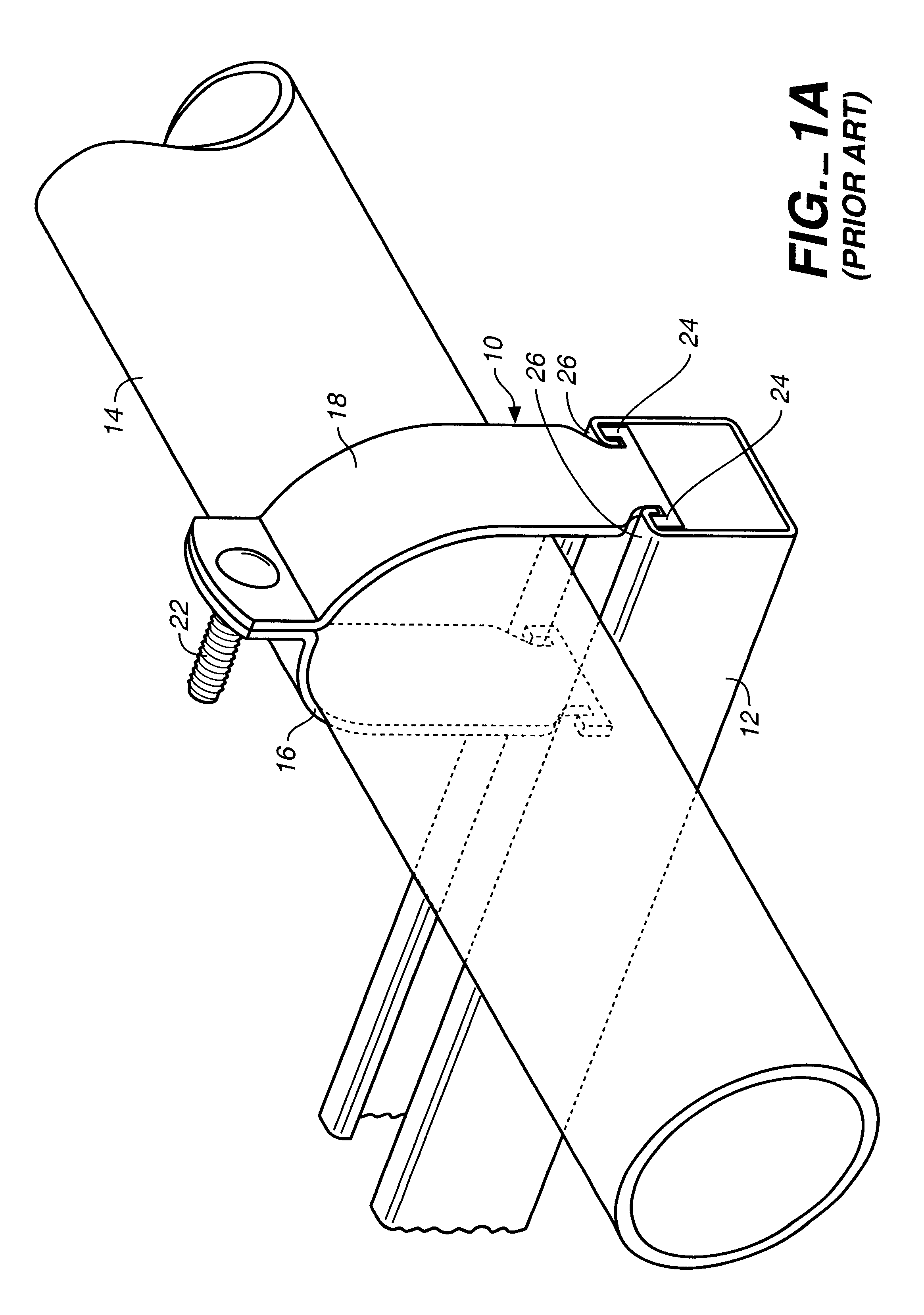
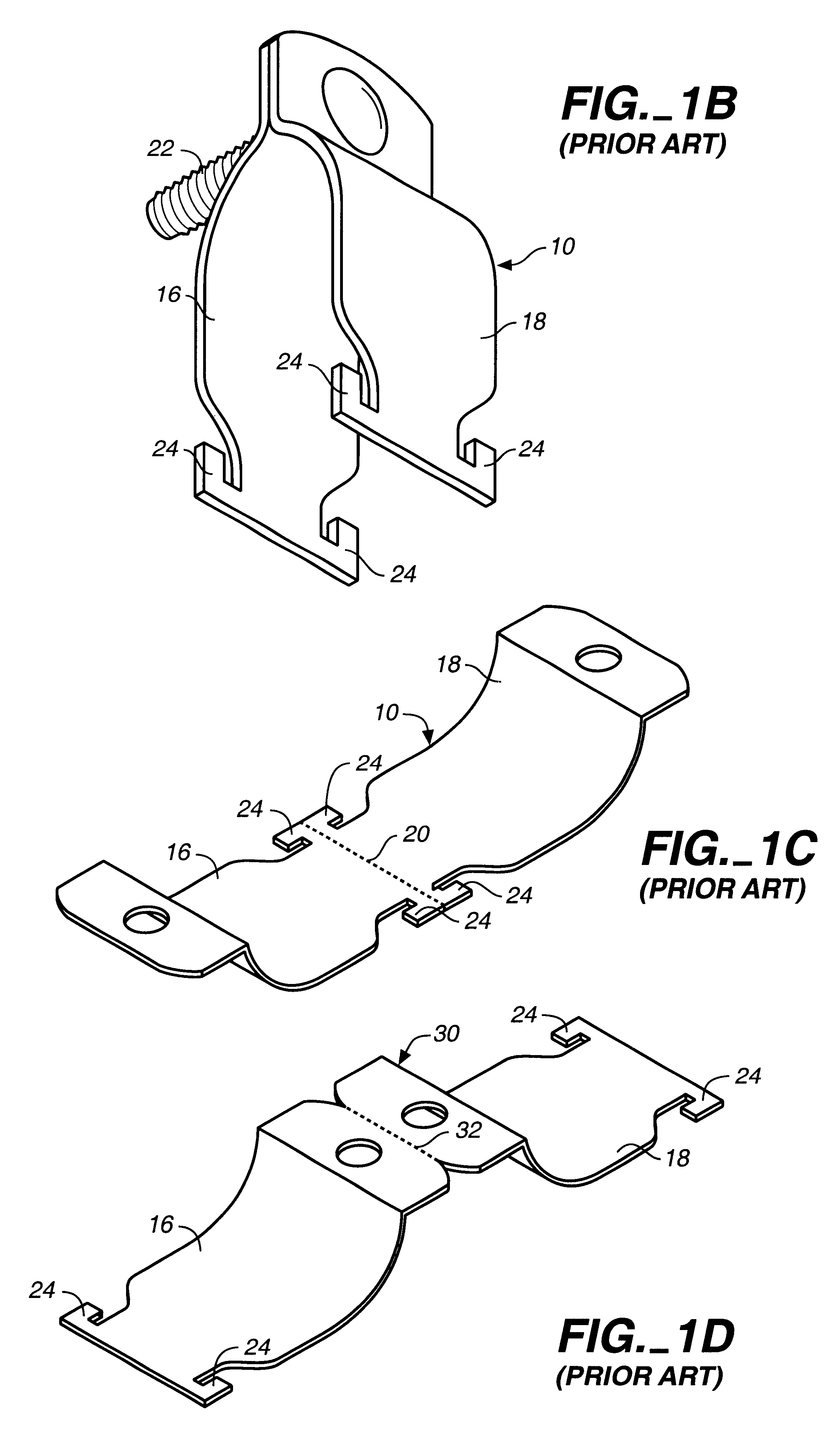
FIGS. 1A-1C illustrate prior art hanger apparatus 10 conventionally employed to support a channel 12 from a conduit 14. The hanger apparatus 10 is often sold in the unitary configuration shown in FIG. 1C. Hanger apparatus 10 includes hanger member legs 16, 18 secured together at ends thereof along a line of weakness 20. The purpose of maintaining this unitary structure is to facilitate shipping and storage. When use is desired, the legs 16, 18 are manipulated and a break is formed along line of weakness 20. The legs 16, 18 are deployed over and on opposite sides of a conduit 14 as shown in FIG. 1A and held together at the upper ends thereof by a mechanical fastener 22.

Located at the other ends of the legs 16, 18 are projections or tabs 24 which project upwardly and are placed in engagement with the underside of lips 26 to support channel 12 from the conduit. It is to be noted that the hanger apparatus of FIGS. 1A-1C is dedicated to such purpose and cannot be used, for example, to su...


PUM


Abstract

Multi-use hanger apparatus includes a hanger member having a hanger member base with an opening formed therein and legs attached to the hanger member base. Spaced projections are attached to the corners of the hanger member base. The hanger member base is formed of hanger member base portions separated by one or more lines of weakness.

Description

This invention relates to multi-purpose hanger apparatus that can be used to support either a channel member or a conduit from building structure.There are many hanger devices and arrangements for supporting conduits or pipes and channels from building structure. Several arrangements particularly devised for such purpose and employed in the prior art are described below. Some hanger devices are particularly designed to support channels and others are particularly devised to support conduits or pipes having a round outer configuration or other configurations. Use of such devices is limited to the particular application for which it is designed. For example, a conventional hanger designed for supporting a channel is not normally useable to support a conduit and vice versa.As will be seen in greater detail below, the hanger apparatus of the present invention has multi-use capability. In one configuration the hanger apparatus can be employed to support a channel from a conduit and in an...

Claims


Application Information

Patent Timeline
Patent Type & Authority Patents(United States)
IPC IPC(8): F16L3/24
CPCF16L3/24Y10S248/909F16L3/243
Inventor ROTH, STEVEN A.
Owner ROTH STEVEN A
Why Eureka
Try Eureka