Closing assistance mechanism for an electrical switchgear apparatus and drive mechanism of an electrical switchgear apparatus equipped with such an assistance mechanism

a technology of assistance mechanism and electrical switchgear, which is applied in the direction of snap-action arrangement, high-tension/heavy-dress switch, switch power arrangement, etc., can solve the problem of coordination problems, the initial power and acceleration of the mechanism and the time required to perform the closing operation, and the choice of the energy storage spring to remain limited

Inactive Publication Date: 2003-02-04
SCHNEIDER ELECTRIC IND SAS
View PDF11 Cites 21 Cited by
  • Summary
  • Abstract
  • Description
  • Claims
  • Application Information

AI Technical Summary

Benefits of technology

The closing assistance mechanism is very simple since it comprises neither a closing latch nor an opening latch, operation thereof being achieved by rotation of the loading shaft. The closing assistance spring enables at least a part of the energy required for closing to be communicated to the switching shaft.

Problems solved by technology

The choice of the energy storage spring does however remain limited by the space available in the mechanism for the spring.
However such a solution assumes that two operating mechanisms coexist, which gives rise to coordination problems, in particular as far as the opening latches and closing latches are concerned.
It does not on the other hand enable the force exerted at the beginning of closing, that conditions the initial power and acceleration of the mechanism and the time required to perform the closing operation, to be increased.

Method used


Image

  • Closing assistance mechanism for an electrical switchgear apparatus and drive mechanism of an electrical switchgear apparatus equipped with such an assistance mechanism
  • Closing assistance mechanism for an electrical switchgear apparatus and drive mechanism of an electrical switchgear apparatus equipped with such an assistance mechanism
  • Closing assistance mechanism for an electrical switchgear apparatus and drive mechanism of an electrical switchgear apparatus equipped with such an assistance mechanism

Examples


Embodiment Construction

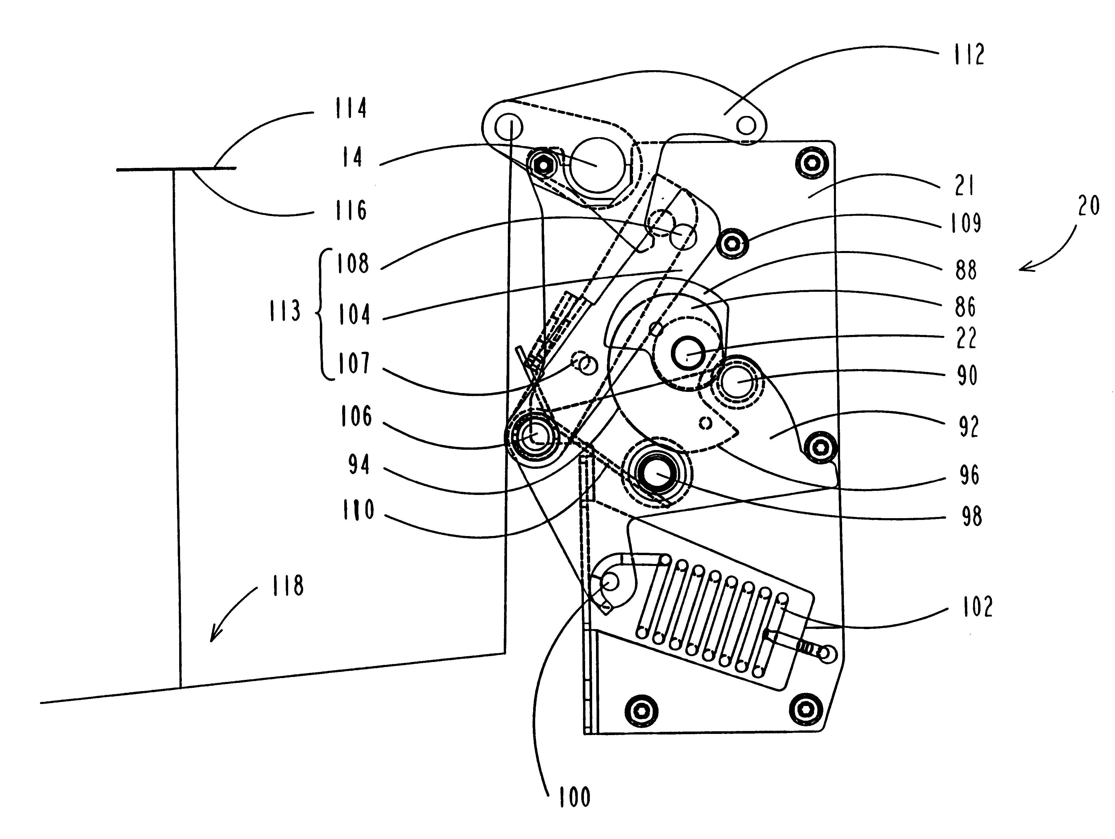
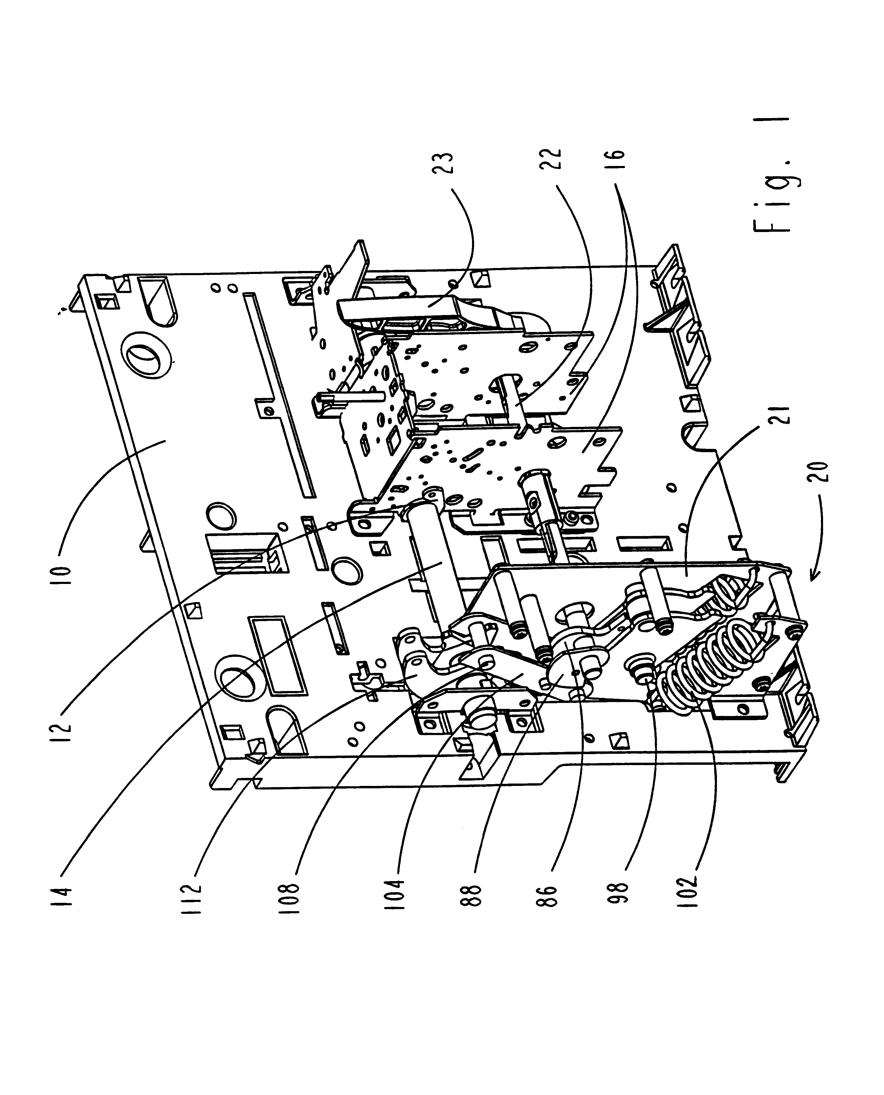
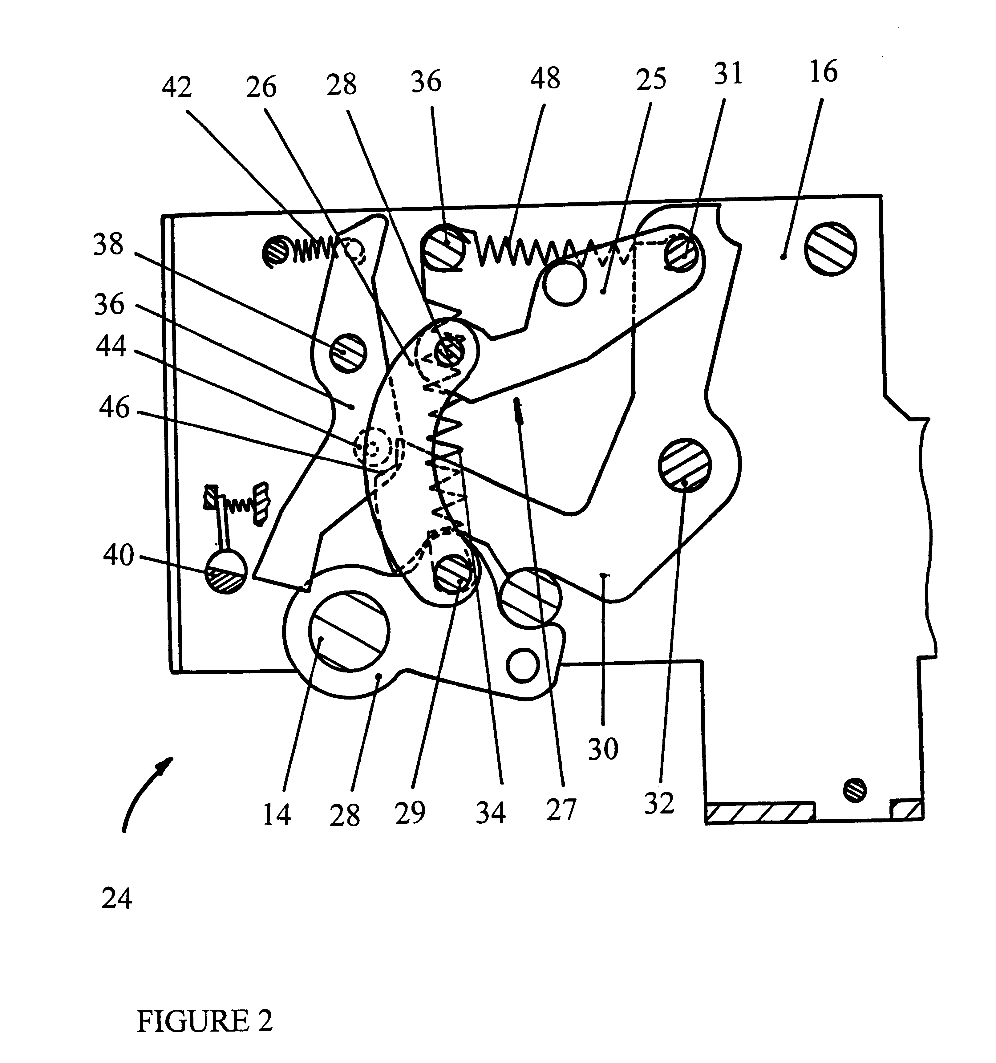
An intermediate plate 10 of a circuit breaker support frame is represented in FIG. 1. Bearings 12 enable a switching shaft 14 to be supported in rotation with respect to the frame 10 between an open position and a closed position. This switching shaft 14 is connected by a kinematic transmission system to at least one pair of separable contacts (not represented) of the circuit breaker so as to drive this pair of contacts between a separated position, corresponding to the open position of the shaft, and a contact position corresponding to the closed position of the shaft. The plate 10 also supports two lateral support flanges 16 of a main drive mechanism of the circuit breaker switching shaft (represented in FIGS. 2 to 4, but purposely omitted in FIG. 1 in order not to complicate reading), and a closing assistance mechanism 20 fitted between a right-hand lateral flange 21 and a left-hand lateral flange (the latter flange having been purposely omitted in the figure). The flanges also e...


PUM


Abstract

A drive mechanism of a circuit breaker comprises a master mechanism and a slave mechanism. The master mechanism is composed of an energy storage sub-assembly comprising an energy storage spring driven by a loading shaft, and an opening and closing sub-assembly driving a switching shaft. The master mechanism is controlled by a closing latch and an opening latch. The slave mechanism comprises a closing assistance spring connected to the loading shaft by means of a loading cam and a multifunctional lever. Rotation of the loading shaft loads the assistance spring and commands relaxation thereof. The assistance spring drives the switching shaft by means of an arm operating in conjunction with a crank in the form of a hook. At the end of closing travel, the arm uncouples from the crank and withdraws so as not to hamper opening of the mechanism. The assistance mechanism enables the energy delivered globally by the drive mechanism to be increased.

Description

The invention relates to a drive mechanism for an electrical switchgear apparatus, in particular for an electrical circuit breaker.STATE OF THE ARTIn the document FR 2,589,626 a drive mechanism of the contacts of an electrical circuit breaker is described comprising an energy storage sub-assembly and an opening and closing sub-assembly. The energy storage sub-assembly comprises an energy storage spring associated to the movable contact in such a way that relaxation of the energy storage spring drives the movable contact to its closed position, and a closing latch designed to latch the energy storage spring in a loaded state. The opening and closing sub-assembly comprises an opening spring and an opening latch designed to latch the opening spring in a loaded state. The opening spring is associated to the movable contact in such a way that relaxation of the opening spring drives the movable contact to an open position and that movement of the movable contact to its closed position cau...

Claims


Application Information

Patent Timeline
Patent Type & Authority Patents(United States)
IPC IPC(8): H01H3/30H01H3/00H01H33/42H01H33/40
CPCH01H3/30H01H3/3015
Inventor MARIN-PACHE, REYNALDBECHARD, ALAINPERRIN, DENIS
Owner SCHNEIDER ELECTRIC IND SAS
Why Eureka
Try Eureka