
Body support for automotive mechanics

Inactive Publication Date: 2003-04-01
AUTOPROD
View PDF21 Cites 29 Cited by
  • Summary
  • Abstract
  • Description
  • Claims
  • Application Information

AI Technical Summary

Benefits of technology

to provide a body support for automotive mechanics that maximizes the physical comfort of a mechanic as he leans over the engine compartment of a vehicle.
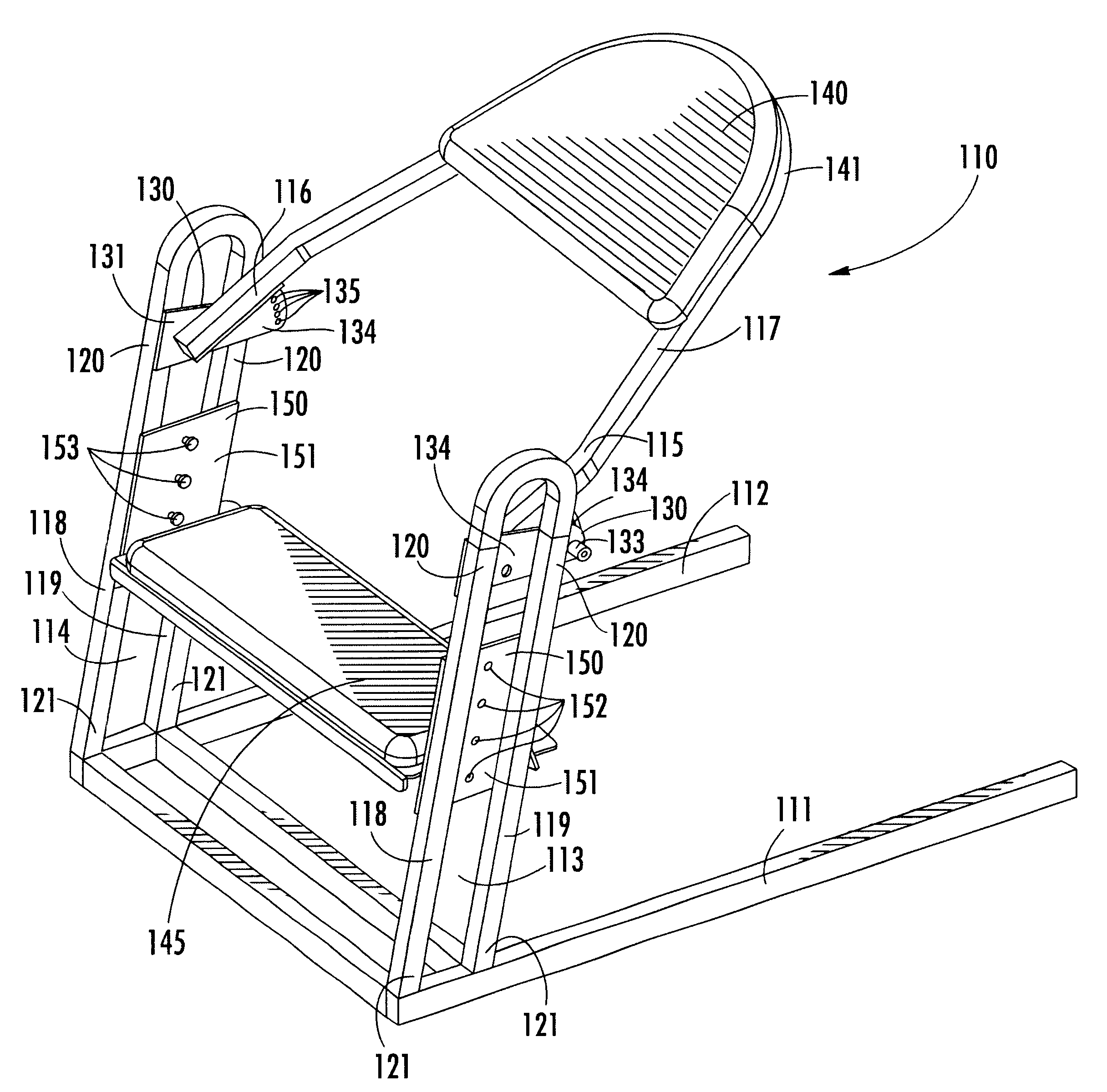
As shown in FIGS. 16 and 17, each pivot 180 includes a plate 181 which is attached to the second ends 172 of one of the respective pairs of tubular support rails 169 and 170. The plate 181 includes a hole 182 defined therethrough, which is adapted for receiving a complementary locking pin 183 therethrough. A bracket 184 is attached to respective ends 185 and 186. The bracket 184 includes holes 187 positioned at spaced-apart intervals along the edge of bracket 184. Each hole 187 is adapted for receiving the complementary locking pin 183 therethrough after the pin 183 has been inserted through the first hole 182. Positioning the pin 153 through the respective holes 182 and 187 in this manner permits the upper support rail 167 to be moved through an arc for adjusting the pitch of a chest pad 190, which is positioned on the support rail 167 for supporting the chest of a mechanic as he leans thereon to work on the engine of a motor vehicle.

Problems solved by technology

In addition, without sufficient lumbar and thoracic support, an automotive mechanic who repeatedly bends over an engine compartment is also at increased risk for spinal injuries, which are often accompanied by neurological and orthopedic complications.
While body supports for mechanics are available, such supports lack features for maximizing the comfort of the mechanic while maintaining the stability of the support.
Such supports also do not provide proper leverage to the mechanic when the support is used in both front-of-vehicle and side-of-vehicle positions.

Method used


Image

  • Body support for automotive mechanics
  • Body support for automotive mechanics
  • Body support for automotive mechanics

Examples


Embodiment Construction

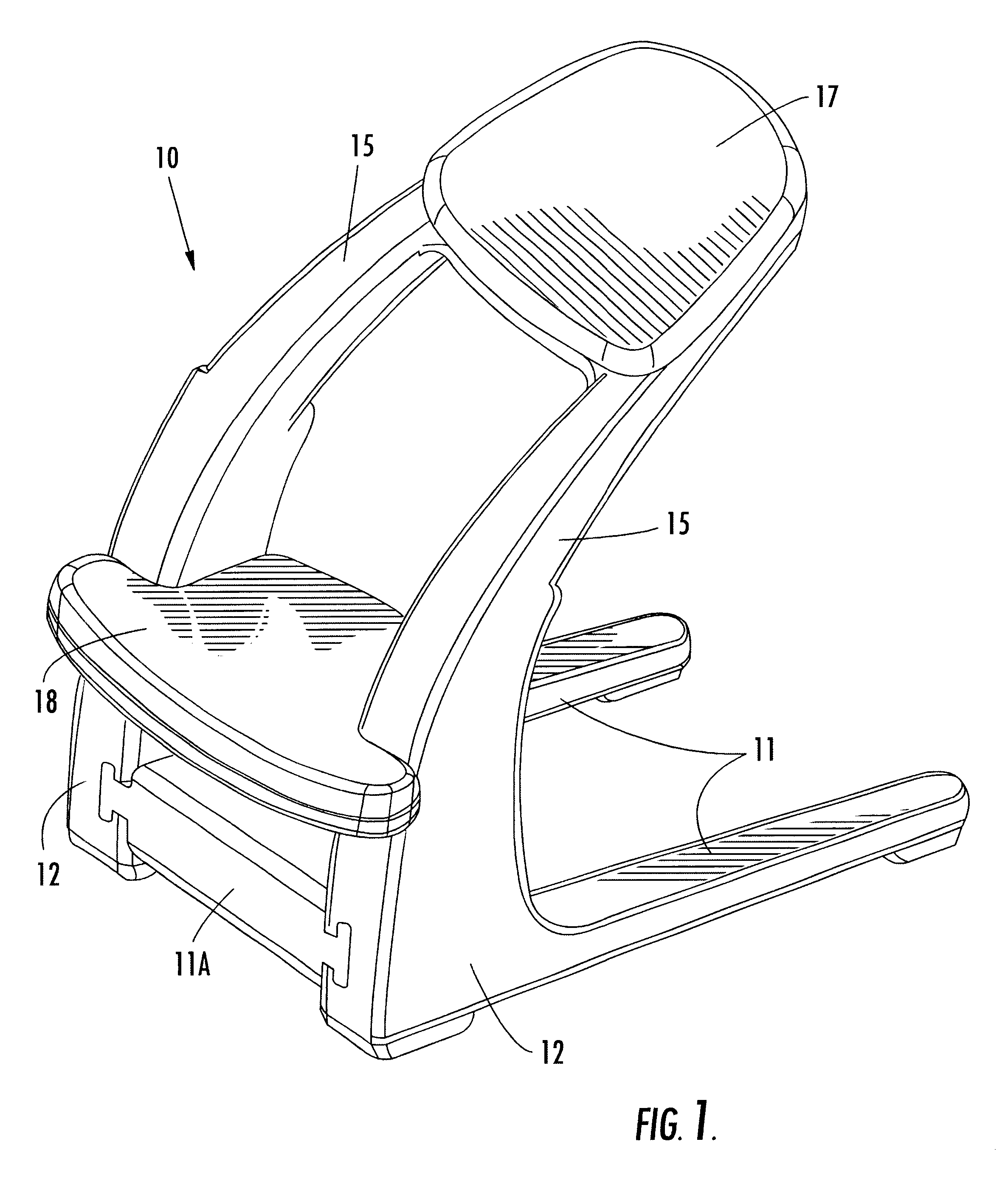
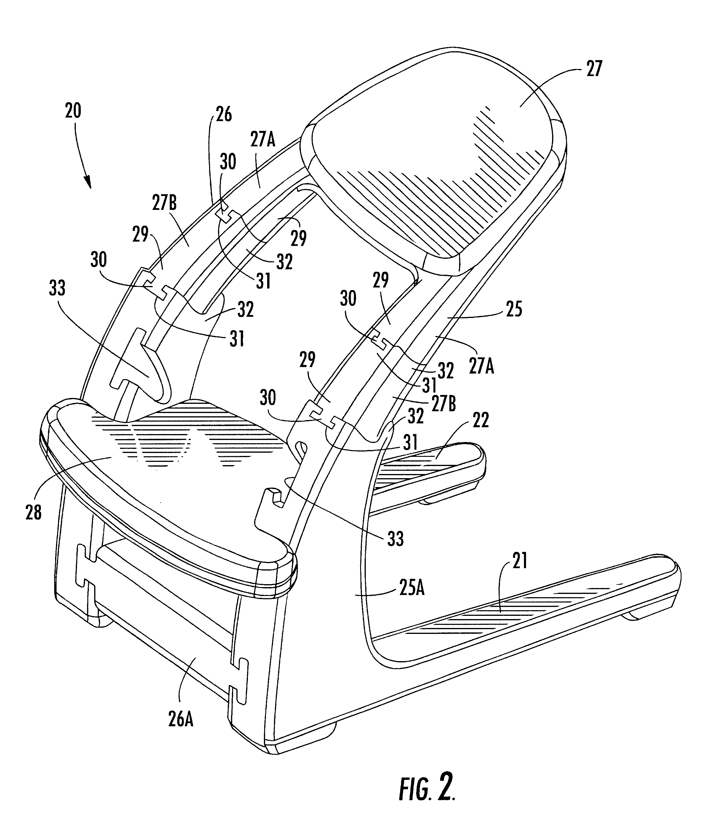
Referring now specifically to the drawings, a mechanic's body support according to one preferred embodiment of the present invention is illustrated in FIG. 1 and shown generally at reference numeral 10. The body support 10 includes first and second horizontally-oriented base rails 11, having respective ends 12 integrally formed with respective first and second support rails 15. Connecting each of the support rails 15 to a respective base rail 11 in this manner permits each support rail 15 to diverge upwardly away from the base rail 11 for permitting the body support 10 to be conveniently positioned either in front or to the side of the engine compartment of a motor vehicle. This allows a mechanic using the body support 10 to lean against the body support 10 for support and position himself over the engine compartment. A cross bar 11A is mounted between the base rails 11 for providing supplemental reinforcement to the body support 10.

As is shown in FIG. 1, the body support 10 also in...


PUM


Abstract

A mechanic's body support including first and second horizontally-oriented and spaced-apart base rails and first and second spaced-apart support rails. Each of the support rails has one end connected to a respective one of the first and second base rails and diverging upwardly from and along the length of the base rails for supporting a mechanic in an elevated position over the engine compartment of a motor vehicle. A chest pad and a knee pad are mounted in spaced-apart relation between the support rails for securing the support rails in a fixed, spaced-apart relation, and for supporting the chest and knees of the mechanic.

Description

TECHNICAL FIELD AND BACKGROUND OF INVENTIONThis invention relates to a body support for mechanics. While the preferred embodiments disclosed herein are of body supports for providing support to mechanics as they repair motor vehicles, the body support of the present invention could clearly be used in any environment where an individual finds it necessary to lean over the equipment, object or project upon which the individual is working, including those involving the provision of medical or veterinary services. Although the vehicle referred to throughout this application is a motor vehicle, it is understood that the invention relates as well to other types of vehicles or equipment including but not limited to airplanes, boats, or other heavy machinery.In many instances, an automotive mechanic working in an automotive repair shop requires an apparatus to lean against or kneel upon which provides more physical support as he leans over engine compartment of a motor vehicle to inspect an...

Claims


Application Information

Patent Timeline
IPC IPC(8): A47C7/50A47C16/00A47C7/00A47C9/02A47C16/04B25H5/00
CPCA47C9/025B25H5/00A47C16/04A47C9/027
Inventor BOTTOMS, GARY D.
Owner AUTOPROD
Learn More