Body support for automotive mechanics

a technology for mechanics and supports, applied in the field of body support for mechanics, can solve the problems of increased risk of spinal injuries for mechanics who repeatedly bend over an engine compartment, lack of features for maximizing comfort and safety, and supports that do not provide proper leverage to mechanics, etc., to achieve the effect of maximizing the physical comfort of mechanics

Inactive Publication Date: 2003-07-22
AUTOPROD
View PDF7 Cites 35 Cited by
  • Summary
  • Abstract
  • Description
  • Claims
  • Application Information

AI Technical Summary

Benefits of technology

to provide a body support for automotive mechanics that maximizes the physical comfort of a mechanic as he kneels over the engine compartment of a vehicle.
Referring now to FIGS. 7 and 8, the body support 10 also includes two hinges 90 that are used to move the body support 10 between an extended use position (see FIG. 7) and a closed storage position (see FIG. 8). As is shown in FIG. 7, a hinge 90 is positioned on the base rail segments 24 and 25 of each base rail section 11 and 12. Each hinge 90 is positioned between the straight end 28 and curved end 29 of each base rail section 11 and 12. As is shown in FIG. 8, the hinges 90 permit the straight ends 28 to be moved toward one another and adjacent shelf 16 so that the body support 10 can be easily stored.

Problems solved by technology

In addition, without sufficient lumbar and thoracic support, an automotive mechanic who repeatedly bends over an engine compartment is also at increased risk for spinal injuries, which are often accompanied by neurological and orthopedic complications.
While body supports for mechanics are available, such supports lack features for maximizing comfort and safety of the mechanic while maintaining the stability of the support.
Such supports also do not provide proper leverage to the mechanic when the support is used in both front-of-vehicle and side-of-vehicle positions.

Method used


Image

  • Body support for automotive mechanics
  • Body support for automotive mechanics
  • Body support for automotive mechanics

Examples


Embodiment Construction

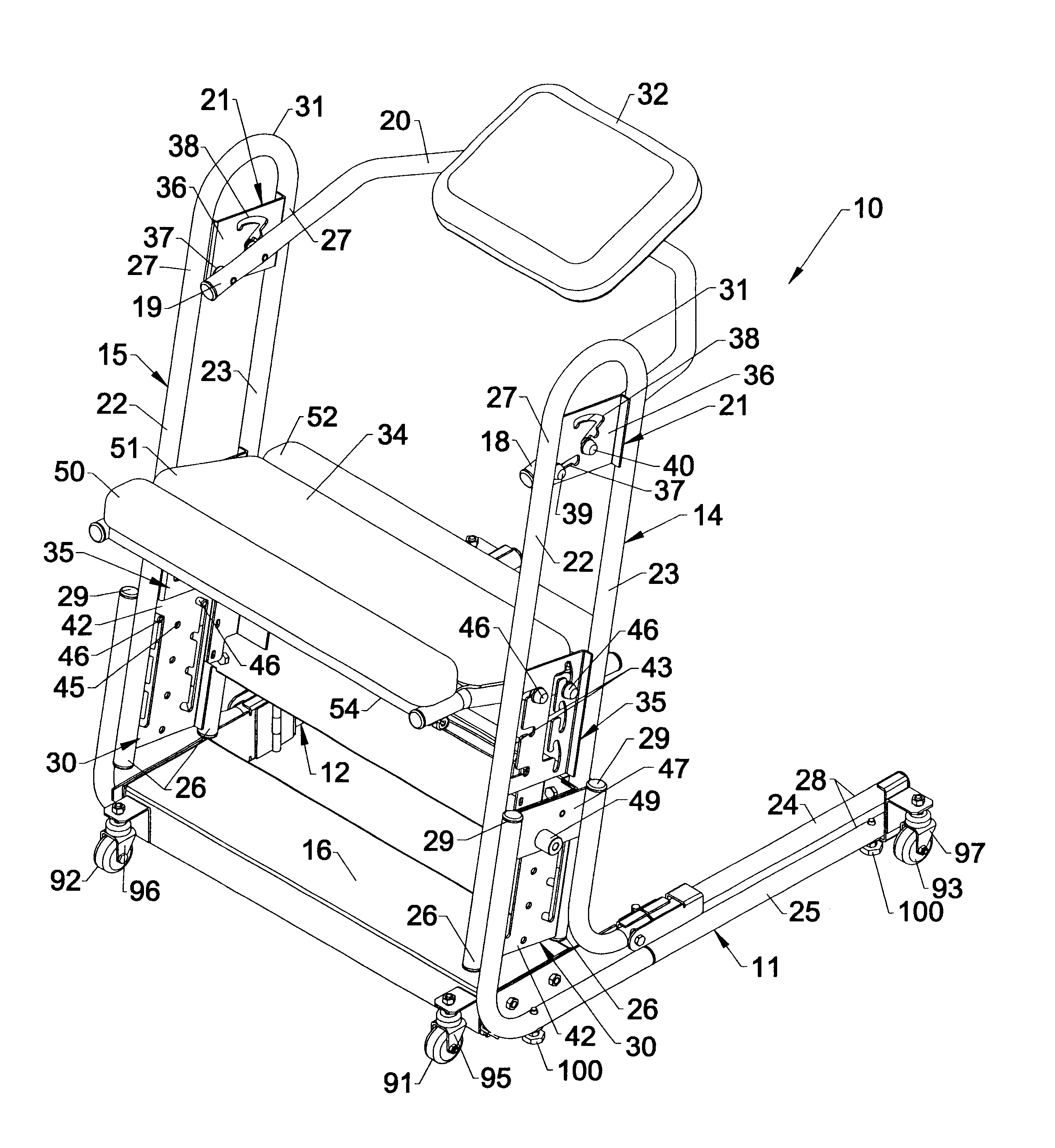
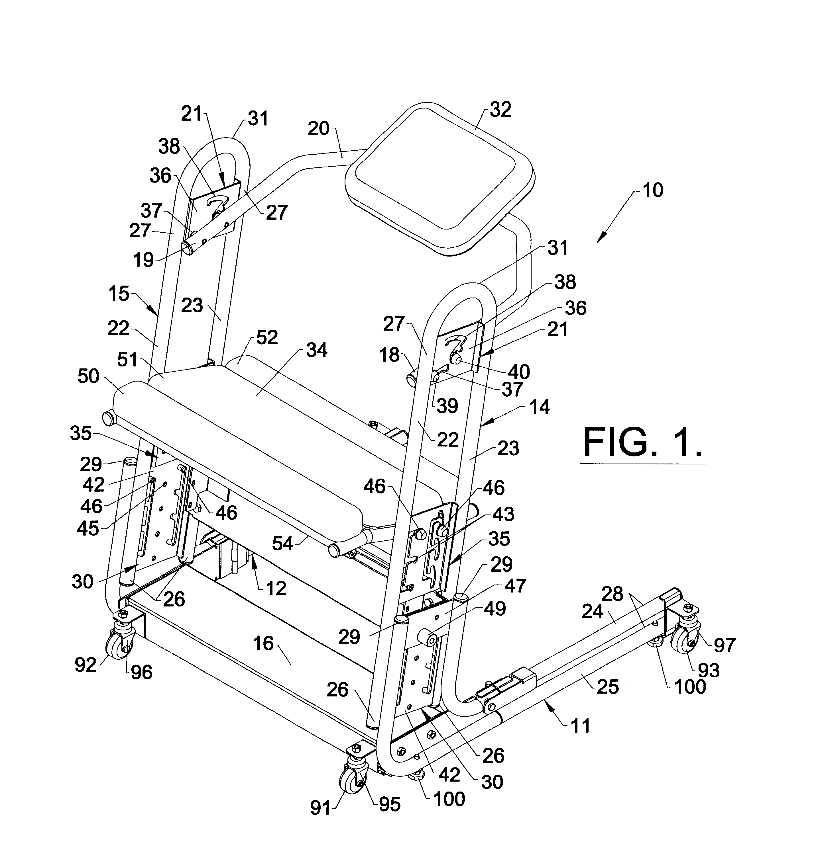
Referring now specifically to the drawings, a mechanic's body support according to one preferred embodiment of the present invention is illustrated in FIG. 1 and shown generally at reference numeral 10. The body support 10 includes first and second horizontally-oriented base rail sections 11 and 12 which are connected to respective first and second vertically-oriented support rail sections 14 and 15 in a manner that permits the support rail sections 14 and 15 to extend upwardly away from respective base rail sections 11 and 12. This allows the body support 10 to be conveniently positioned either in front or to the side of the engine compartment of a motor vehicle so that a mechanic using the body support 10 can lean against the body support 10 for support and position himself over the engine compartment. A cross-support-member 16 is mounted between the base rail sections 11 and 12 for connecting the base rail sections 11 and 12 together.

Support rail sections 14 and 15 are attached t...


PUM


Abstract

A mechanic's body support including first and second horizontally-oriented and spaced-apart base rails and first and second spaced-apart support rails. Each of the support rails has one end connected to a respective one of the first and second base rails. Each support rail also extends upwardly from and is in vertical alignment with the base rails for supporting a mechanic as he kneels in an elevated position over the engine compartment of a motor vehicle. A chest pad and a knee pad are mounted in spaced-apart relation between the support rails for securing the support rails in a fixed, spaced-apart relation, and for supporting the chest and knees of the mechanic while in the kneeling position, thus allowing the skeletal structure of the body to support the weight, rather than the back and leg muscles.

Description

TECHNICAL FIELD AND BACKGROUND OF INVENTIONThis application is a continuation-in-part application and relates to U.S. patent application Ser. No. 09 / 599,670, filed on Jun. 22, 2000, and claims priority to that non-provisional application, which in turn relates to U.S. Provisional Patent Application Ser. No. 60 / 140,668 filed on Jun. 24, 1999, and claims priority to that provisional application.This invention relates to a body support for mechanics. While the preferred embodiments disclosed herein are of body supports for providing support to mechanics as they repair motor vehicles, the body support of the present invention could clearly be used in any environment where an individual finds it necessary to lean over the equipment, object or project upon which the individual is working, including those involving the provision of medical or veterinary services. Although the vehicle referred to throughout this application is a motor vehicle, it is understood that the invention relates as ...

Claims


Application Information

Patent Timeline
Patent Type & Authority Patents(United States)
IPC IPC(8): A47C7/50A47C16/00A47C7/00A47C9/02A47C16/04B25H5/00
CPCA47C9/025A47C9/027A47C16/04B25H5/00
Inventor BOTTOMS, GARY D.
Owner AUTOPROD
Why Eureka
Try Eureka