Apparatus and method for phase lock loop gain control using unit current sources

a gain control and phase lock loop technology, applied in the direction of oscillation generators, seperate pre-tuned circuit tuning, resonance circuit tuning, etc., can solve the problems of variable vco gain, variable vco gain, and prone to instability of feedback loops

a gain control and phase lock loop technology, applied in the direction of oscillation generators, seperate pre-tuned circuit tuning, resonance circuit tuning, etc., can solve the problems of variable vco gain, variable vco gain, and prone to instability of feedback loops

US6583675B2Inactive Publication Date: 2003-06-24AVAGO TECH INT SALES PTE LTD

Image

  • Apparatus and method for phase lock loop gain control using unit current sources
  • Apparatus and method for phase lock loop gain control using unit current sources
  • Apparatus and method for phase lock loop gain control using unit current sources

Examples


Embodiment Construction

Before describing the invention in detail, it is useful to describe an example tuner application for the invention. The invention is not limited to the tuner application that is described here, and is applicable to other tuner and nontuner applications as will be understood to those skilled in the relevant arts based on the discussions given herein.

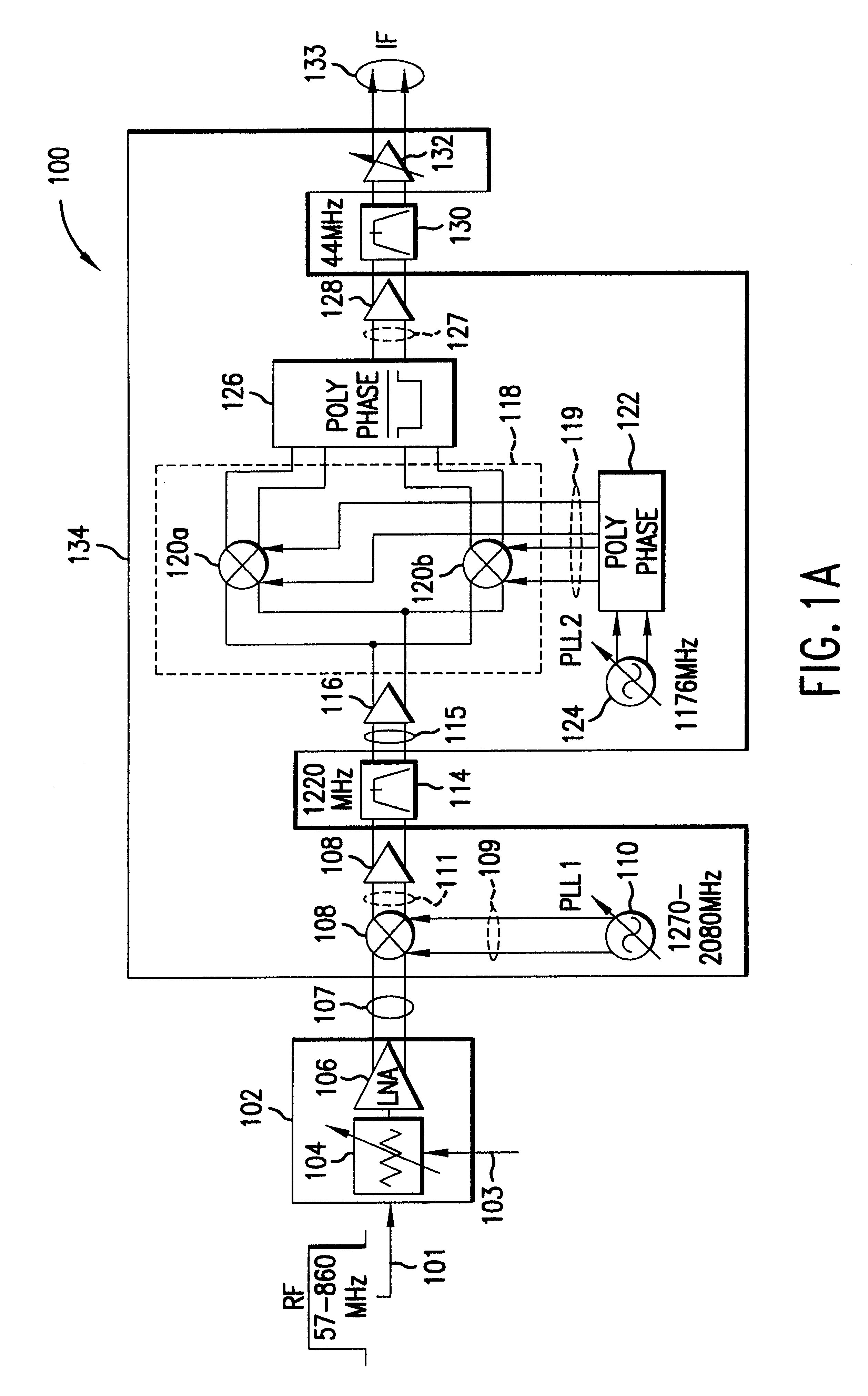
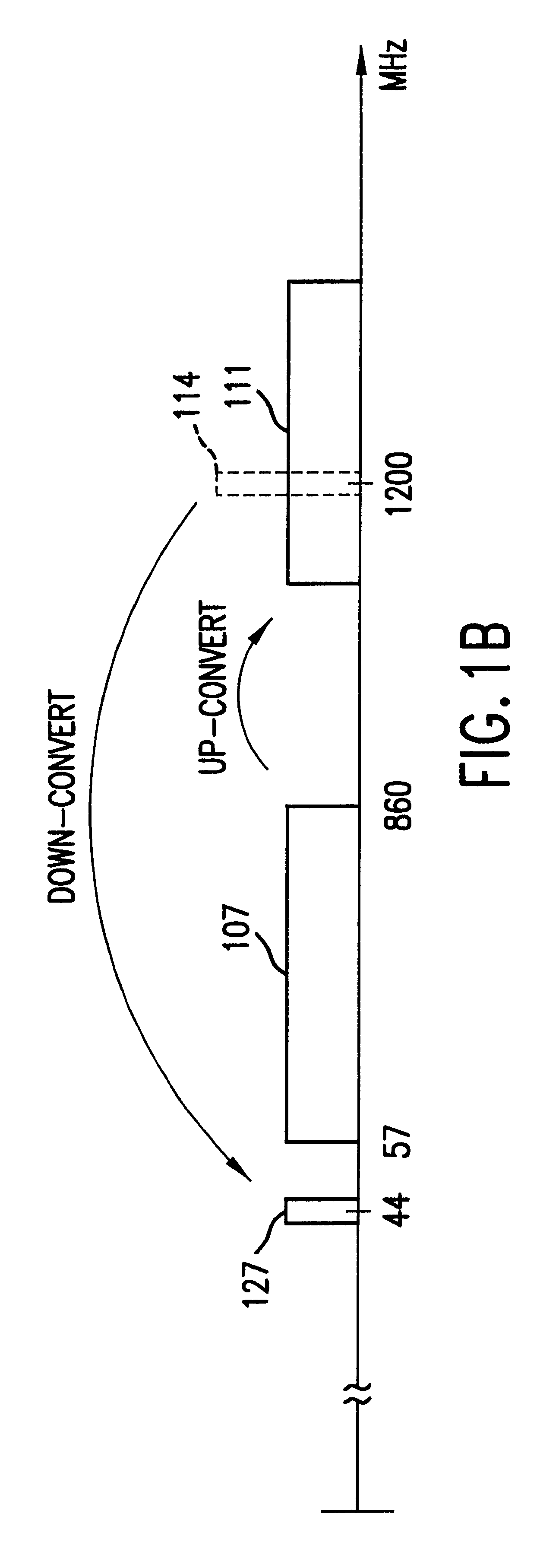
FIG. 1A illustrates a schematic of a tuner assembly 100 that has an RF automatic gain control circuit (AGC) 102, and a tuner 134. The tuner assembly 100 receives an RF input signal 101 having multiple channels and down-converts a selected channel to an IF frequency, to produce an IF signal 133. For instance, the RF input signal 101 can include multiple TV channels that typically have 6 MHZ frequency spacings and cover a range of 57-860 MHZ, and where the selected channel is down-converted to an IF frequency at 44 MHZ, 36 MHZ or some other desired IF frequency for further processing. The structure and operation of the AGC circuit 102 and t...


PUM


Abstract

A gain compensator compensates for the gain variation of a varactor-tuned voltage tuned oscillator (VCO) in a phase lock loop (PLL). The VCO includes a parallel LC circuit having multiple fixed capacitors that can be switched-in or switched-out of the LC circuit according to a capacitor control signal to perform band-select tuning of the VCO. The gain compensator compensates for the variable VCO gain by generating a charge pump reference current that is based on the same capacitor control signal that controls the fixed capacitors in the LC circuit. The gain compensator generates the charge pump reference current by replicating a reference scale current using unit current sources. The number of times the reference scale current is replicated is based on the fixed capacitance that is switched-in to the LC circuit and therefore the frequency band of the PLL. The reference scale current is generated based on a PLL control that specifics certain PLL characteristics such as reference frequency, loop bandwidth, and loop damping. Therefore, the reference pump current can be efficiently optimized for changing PLL operating conditions, in addition to compensating for variable VCO gain.

Description

1. Field of the InventionThe present invention generally relates to gain control in a phase lock loop, and more specifically to phase lock loop gain control using scaled unit current sources.2. Background ArtRadio frequency (RF) transmitters and receivers perform frequency translation by mixing an input signal with a local oscillator (LO) signal.Preferably, the LO signal should have a frequency spectrum that is as close to a pure tone as possible in order to maximize system performance during the signal mixing operation. The deviation of the LO signal from a pure tone is quantified as phase noise or phase jitter, and is generally referred to as spectral purity. In other words, a LO signal with good spectral purity has low phase noise.Phase-locked loops (PLLs) are often used in frequency synthesizers to generate the LO signal. A PLL frequency synthesizer produces an output signal, typically a sinewave or square wave, that is a frequency multiple of an input reference signal. The PLL ...

Claims


Application Information

Patent Timeline
24 Jun 2003
Publication
US6583675B2
IPC
H03L7/099; H03D7/00; H03L7/08; H03D7/18; H03L7/089; H03J5/24; H03L7/00; H03L7/16; H03J5/00; H03L7/18; H03B5/08; H03B5/12; H03B1/00; H03L7/10
CPC
H03L7/1072; H03D7/165; H03D7/18; H03J5/244; H03L7/00; H03L7/0898; H03L7/093; H03L7/099
Inventors
GOMEZ, RAMON A.