Goggles

a technology of goggles and lenses, applied in the field of goggles, can solve the problems of affecting the anti-fog effect of the goggles, the cloudy proportion of the goggles corresponding to them (or both side portions of the goggles), and the inability to obtain sufficient anti-fog effect at both side portions of the goggles

Inactive Publication Date: 2003-08-05
SWANS
View PDF17 Cites 47 Cited by
  • Summary
  • Abstract
  • Description
  • Claims
  • Application Information

AI Technical Summary

Problems solved by technology

However, since the skier's cheekbones and their neighborhood become most closer to the inner surfaces of the goggles, the portions of goggle lenses corresponding to them (or both side portions of the goggles) are often clouded up.
Consequently, if such goggles are used in today's skiing or the like which requires a large quantity of motion, a sufficient anti-fog effect cannot necessarily be obtained at the both side portions of the goggles.

Method used


Image

  • Goggles
  • Goggles
  • Goggles

Examples


Embodiment Construction

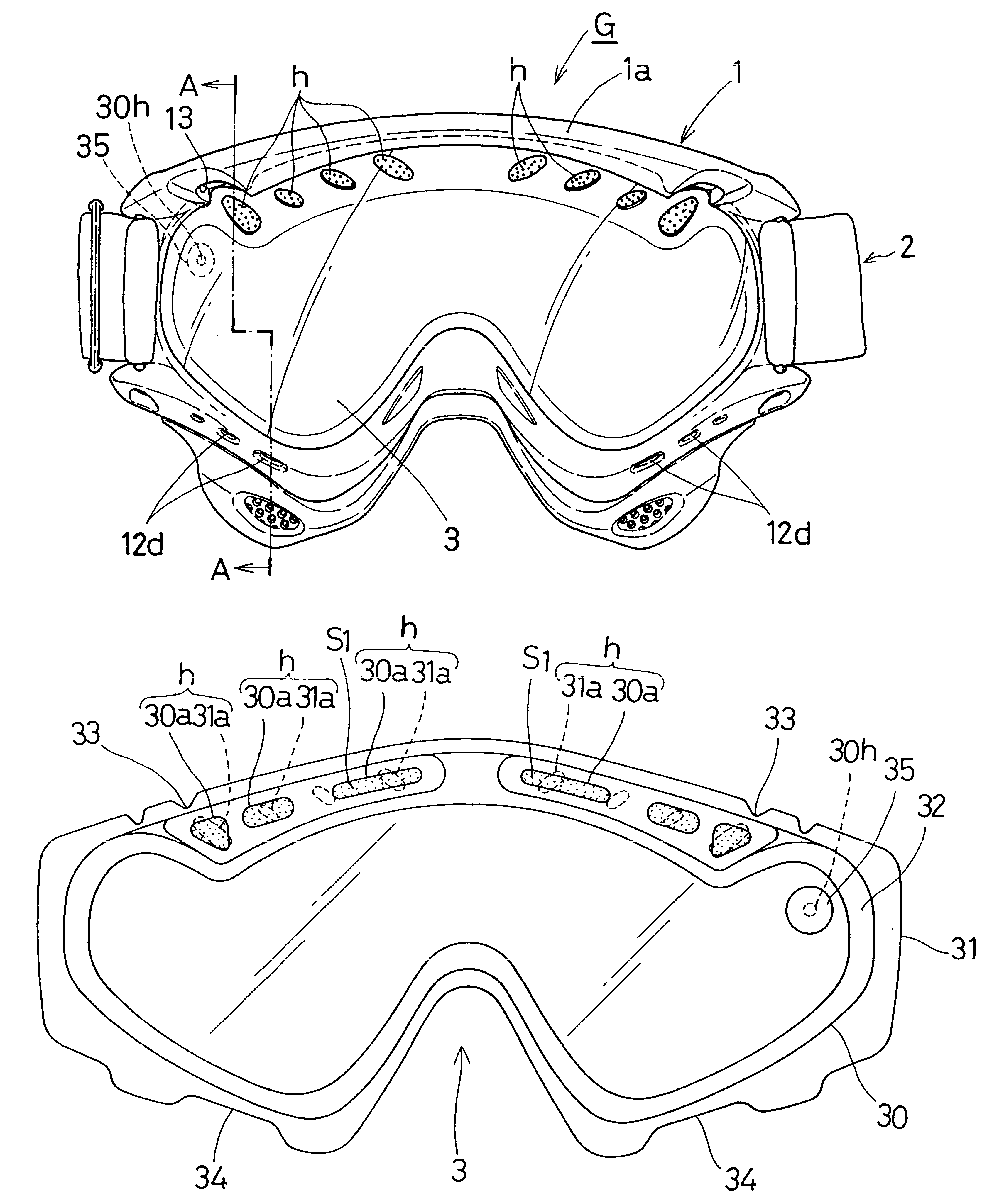
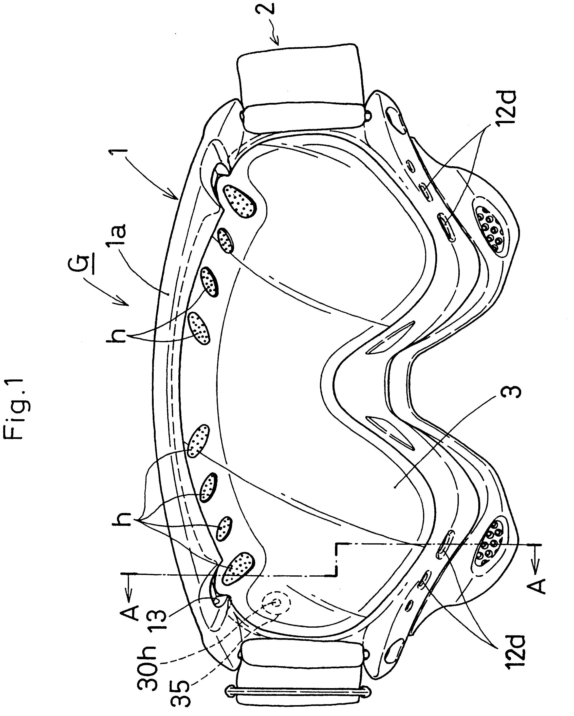
FIG. 1 is a front view of skiing goggles G. FIG. 7 is a view of a goggle lens 3 used in the goggles G, which is seen from a side of an inner lens plate 30. As shown in FIGS. 1 and 2, the goggles G include a goggle frame 1, an expandable, elastic band 2 coupled to the goggle frame 1, and a goggle lens 3 detachably fitted into the goggle frame 1.

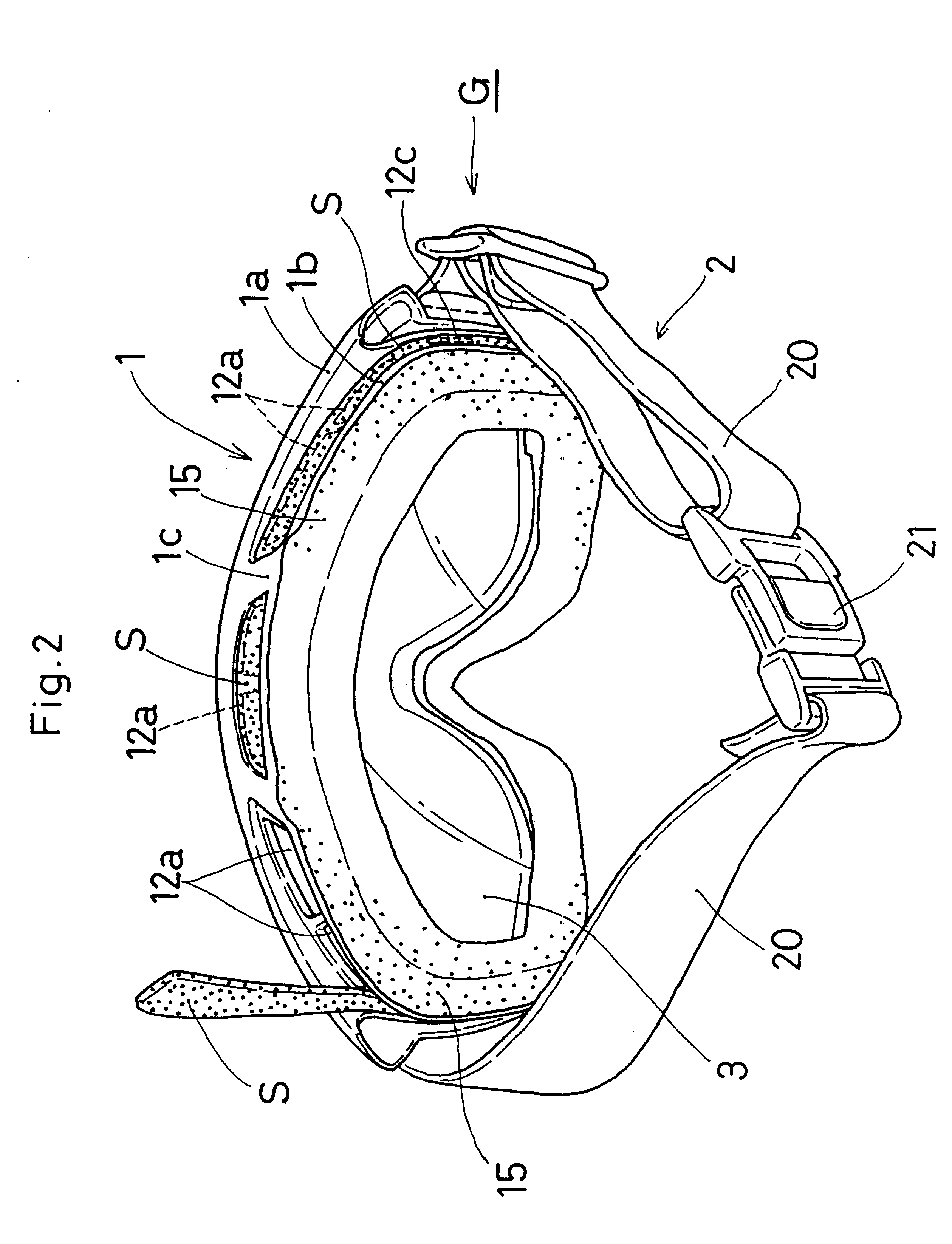
The goggle frame 1 is made of soft material such as an elastic synthetic resin, rubber or the like. As shown in FIGS. 2 and 3, the goggle frame 1 includes a lens fitting edge 1a, a face abutment section 1b and a peripheral wall section 1c connecting the lens fitting edge 1a to the face abutment section 1b. The goggle lens 3 is detachably fitted into the lens fitting edge 1a.

As shown in FIG. 3, the lens fitting edge 1a is provided with a groove 10 in which an outer peripheral edge of the goggle lens 3 is received. The groove 10 is constituted with a front wall 11 and a rear wall 12. As shown in FIG. 4, air vent openings 13 and 14 are provided o...


PUM


Abstract

Goggles include a goggle frame, a goggle lens to be detachably fitted in a groove formed on the inner peripheral portion of the goggle frame. The goggles are provided with a plurality of vent holes in an upper area in the goggle lens. The vent holes located on the both sides are made larger than those in the center.

Description

The present invention relates to goggles, more particularly relates to goggles used for skiing and snowboarding.PRIOR ARTGoggles of this type usually have ventilation sections to prevent inner surfaces of goggle lenses from becoming clouded up with a skier's body temperature, sweating or the like. However, since the skier's cheekbones and their neighborhood become most closer to the inner surfaces of the goggles, the portions of goggle lenses corresponding to them (or both side portions of the goggles) are often clouded up. In view of this, goggles with ventilation sections having a plurality of vent holes above the goggle lenses have recently become available in the market.However, all the plural vent holes of these conventional goggles are the same in size, or the central vent holes are formed smaller than the side vent holes. Consequently, if such goggles are used in today's skiing or the like which requires a large quantity of motion, a sufficient anti-fog effect cannot necessar...

Claims


Application Information

Patent Timeline
Patent Type & Authority Patents(United States)
IPC IPC(8): A61F9/02A63B33/00
CPCA61F9/028A61F9/02
Inventor TSUBOOKA, TORU
Owner SWANS
Why Eureka
Try Eureka