Motor operated stapler

a motor-operated, stapler technology, applied in the direction of stapling tools, nailing tools, manufacturing tools, etc., can solve the problem of not being able to bend the proportions

Inactive Publication Date: 2004-03-02
MAX CO LTD
View PDF13 Cites 79 Cited by
  • Summary
  • Abstract
  • Description
  • Claims
  • Application Information

AI Technical Summary

Benefits of technology

In the third aspect of the present invention there is provided, in combination with the above first aspect, a motor-operated stapler further including a clincher pivoting mechanism for moving the clinchers pivotally, the clincher pivoting mechanism comprising clincher links installed on the clincher base to move the clinchers vertically pivotally, driven cam surfaces formed respectively on the clincher links and extending in the thickness direction of the bundles of sheets to be stapled, fulcrums which convert swing motions of the cam surfaces into pivotal motions of the clinchers, and driving cams installed on fixing means side which hold the magazine, the driving cams coming into contact with the driven cam surfaces of the clincher links and being rotated by the drive source provided on the magazine side, and wherein the clinchers' pivotal movement control means are constructed so that when the thickness of the bundle of sheets exceeds a predetermined value with respect to the length of staple leg portions, the distance between an abutment position and each of the fulcrums which abutment position is the position of abutment between each of the clincher links and each of the clinchers is increased relatively with respect to the distance between an abutment position and each of the fulcrums which abutment position is the position of abutment between each of the clincher links and each of the driving cams.

Problems solved by technology

Consequently, the amount of the pivotal movement for bending the staple leg portions projecting from the bundle of sheets to be stapled becomes small and there easily occurs a case where the leg portions cannot be bent sufficiently, with consequent occurrence of inconveniences such as the copying paper bundle being caught on projections or the like formed on a desk.

Method used


Image

  • Motor operated stapler
  • Motor operated stapler
  • Motor operated stapler

Examples


Embodiment Construction

A motor-operated stapler embodying the present invention will be described hereinunder with reference to the accompanying drawings.

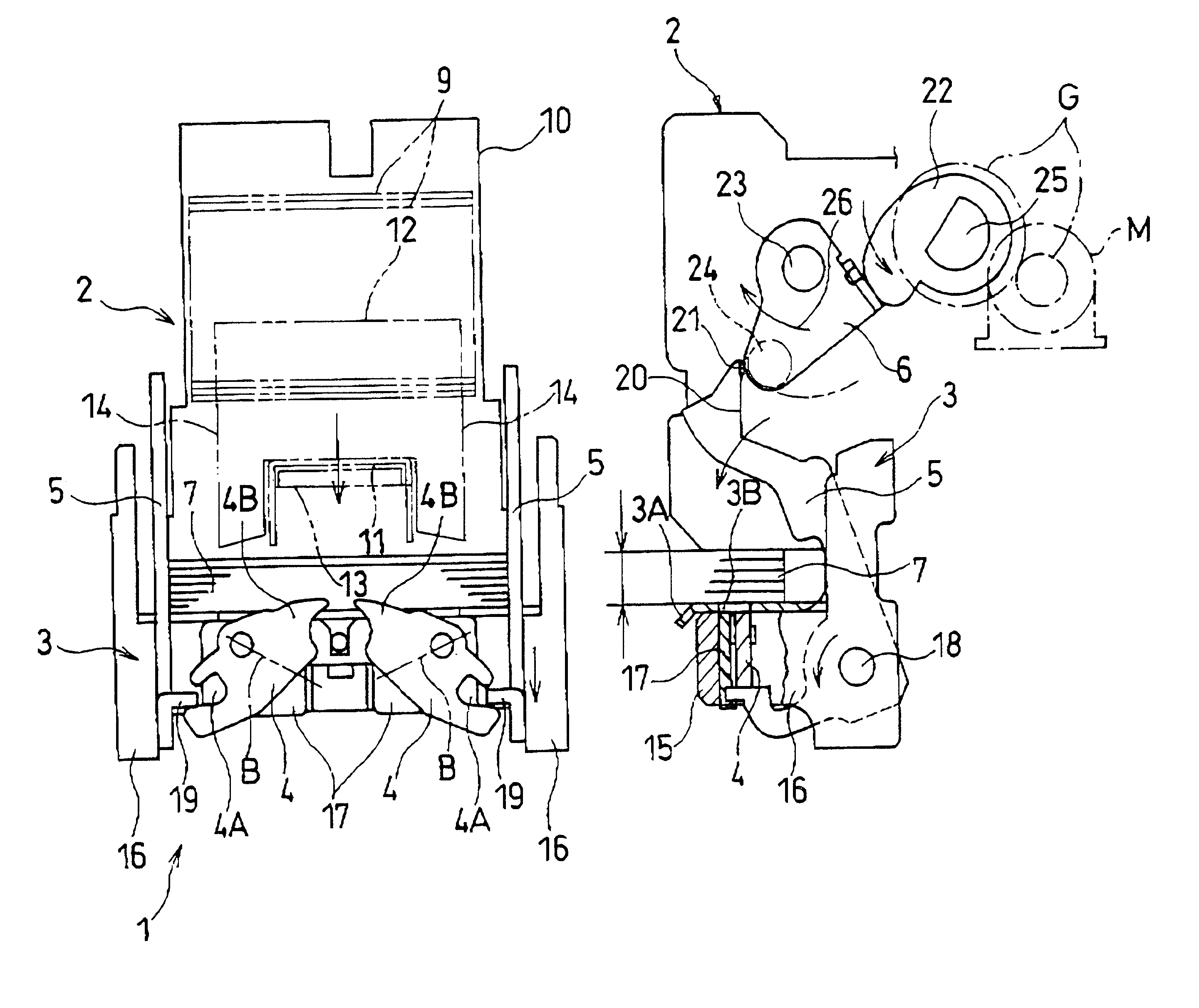
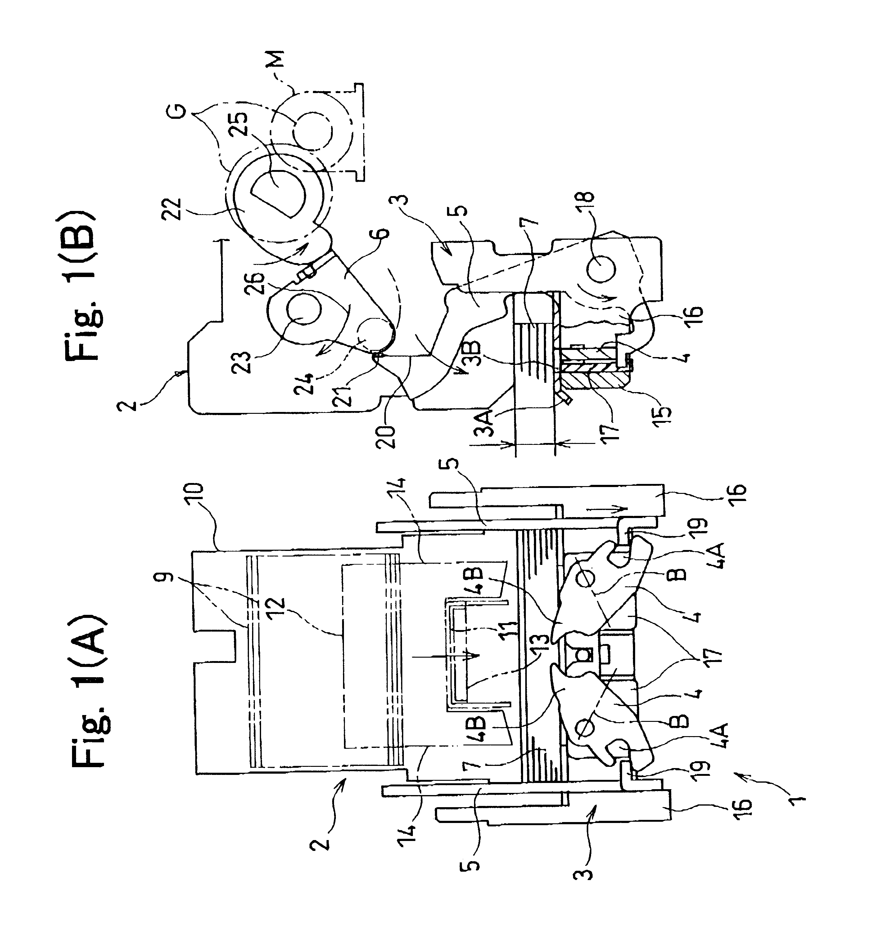
FIG. 1 illustrates the configuration of a principal mechanism for driving clinchers in the motor-operated stapler which is indicated at 1. In the same figure, the reference numeral 2 denotes a magazine, the numeral 3 denotes a clincher base, numeral 4 denotes a clincher, numeral 5 denotes a clincher link, numeral 6 denotes a driving cam, and numeral 7 denotes a bundle of sheets to be stapled.

The motor-operated stapler 1 is also provided with other mechanisms than the mechanism shown in FIG. 1, such as a control unit and a driver motor, but a principal mechanism for driving clinchers is shown in FIG. 1.

The magazine 2 has a cartridge 10 which receives therein a large number of joined staple members 9 in a stacked state, the joined staple members 9 each comprising straight wire-like staples 11 which are joined together in the shape of sheet, and a well know...


PUM

PropertyMeasurementUnit
thicknessaaaaaaaaaa
angleaaaaaaaaaa
areasaaaaaaaaaa

Abstract

A motor-operated stapler is disclosed which, when a bundle of sheets to be stapled is thin, prevents staple leg portions once inserted through the bundle of sheets from again piercing through the sheets bundle and which, in the case of a thick bundle of sheets, bends staple leg portions sufficiently to staple the bundle of sheets to a satisfactory extent. In the motor-operated stapler, a clincher base which carries a bundle of sheets thereon is supported by a housing of a magazine which pushes out a U-shaped staple downward, the bundle of sheets is pinched by both the clincher base and the magazine, the U-shaped staple is pushed out from the magazine into and through the bundle of sheets, and a pair of leg portions of the staple thus projected from the bundle of sheets are bent by a pair of clinchers installed on the clincher base.

Description

1. Field of the InventionThe present invention relates to a motor-operated stapler for bending leg portions of a staple in a well-shaped state along a bundle of sheets to be stapled irrespective of the thickness of the bundle of sheets.2. Description of the Prior ArtHeretofore there has been known a stack tray of a copying machine which tray is provided with a motor-operated stapler. In this motor-operated stapler, a large number of rectilinear wires are arranged in parallel to form sheet-like staples, then a large number of such sheet-like staples are stacked within a cartridge and are sent out one by one from a delivery port formed in the cartridge. The cartridge can be accommodated with a magazine which is provided with staple forming / drive-out means.Below the magazine is disposed a clincher base having a flat paper carrying surface for carrying a copying paper bundle thereon. The clincher base is slidably vertically with respect to the magazine so that the copying paper carrying...

Claims


Application Information

Patent Timeline
Patent Type & Authority Patents(United States)
IPC IPC(8): B27F7/21B27F7/00B25C5/04B25C5/15B27F7/19
CPCB27F7/21
Inventor HAKOZAKI, KATSUYAABE, SHINYA
Owner MAX CO LTD
Why Eureka
Try Eureka