Systems and methods for operating fluid ejection systems using a print head preparatory firing sequence

a technology of operating fluid and firing sequence, which is applied in the direction of printing, other printing apparatus, etc., can solve the problems of affecting the ejection quality

a technology of operating fluid and firing sequence, which is applied in the direction of printing, other printing apparatus, etc., can solve the problems of affecting the ejection quality

US6739693B1Inactive Publication Date: 2004-05-25XEROX CORP

Image

  • Systems and methods for operating fluid ejection systems using a print head preparatory firing sequence
  • Systems and methods for operating fluid ejection systems using a print head preparatory firing sequence
  • Systems and methods for operating fluid ejection systems using a print head preparatory firing sequence

Examples


Embodiment Construction

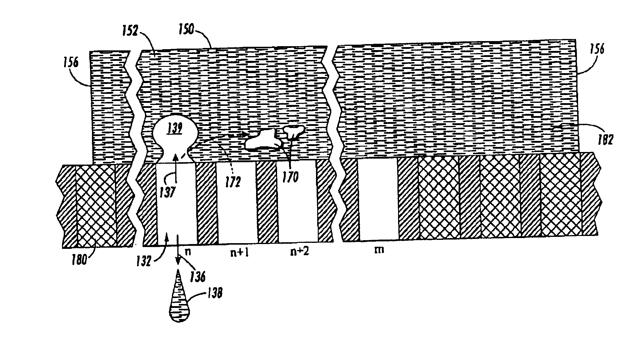
Various exemplary embodiments of the systems and methods according to this invention allow fluid ejection systems to be maintained by using firing sequences of the fluid ejectors according to this invention. The mechanisms and techniques used for fluid ejection according to this invention allow moveable contaminants, bubbles, debris, residue and / or deposits or the like within a fluid supply manifold and / or inlet filters to be moved from ejector channel inlets using a back pressure wave resulting from firing of the fluid ejectors. In various exemplary embodiments, contaminants, bubbles, debris, residue and / or deposits or the like are moved within the fluid supply manifold in the direction of the firing sequence of the fluid ejectors.

In general, the contaminants, bubbles, debris, residue and / or deposits or the like dislodged by firing the fluid ejectors are moved into less-harmful positions within the fluid supply manifold. Such less harmful positions within the fluid supply manifold ...


PUM


Abstract

Current fluid ejector maintenance techniques do not adequately deal with moveable debris particles present in the fluid supply manifold. Such moveable particles within the fluid supply manifold of a fluid ejector head can cause random ejection defects by clogging, restricting and / or blocking the channel inlets and / or filters present in the channel inlets, causing missed or misfired and / of misdirected drops. At least some of a plurality of fluid ejectors can be fired in a sequential pattern. Sequentially firing the fluid ejectors can move movable particles in the direction of the firing sequence. The moved movable particles can be deposited into non-operative areas within the fluid supply manifold, such as, for example, non-firing fluid ejection locations. The fluid ejectors can be fired in a sequential pattern within blocks of the fluid ejectors. For example, a fluid ejector head with 120 fluid ejectors can fire 1 out of every 20 fluid ejectors.

Description

1. Field of InventionThis invention is directed to systems and methods for maintaining and / or enhancing operation of fluid ejection systems.2. Description of Related ArtFluid ejection systems, such as drop on demand liquid ink printers, use various methods to eject fluids, including but no limited to piezoelectric, acoustic, phase change, wax based and thermal systems. These systems include at least one fluid ejector from which droplets of fluid are ejected towards a receiving medium, such as a sheet of paper. A channel is defined within each fluid ejector. The fluid is disposed in the channel. Droplets of fluid can be expelled as required from orifices or nozzles at the end of the channels using power pulses.In some fluid ejection systems, such as, for example, drop on demand thermal ink jet printers, a pressurized reservoir of ink is connected to a plurality of ink channels and, subsequently, the nozzles, via a fluid supply manifold. The fluid supply manifold contains internal, cl...

Claims


Application Information

Patent Timeline
25 May 2004
Publication
US6739693B1
IPC
B41J2/17; B41J2/165
CPC
B41J2/16526; B41J2/1707
Inventors
FERRINGER, MICHAEL C.