Imaging device and method

a projectile and projectile technology, applied in the field of projectiles, can solve the problems of unable to resist the high g, render the imaging process impossible, and useless images

Inactive Publication Date: 2004-07-20
GEO T VISION
View PDF21 Cites 19 Cited by
  • Summary
  • Abstract
  • Description
  • Claims
  • Application Information

AI Technical Summary

Problems solved by technology

However, the above disclosed references involve some technical drawbacks such as, for example, some of the above references are not designed to withstand the high G shock during launching which can range between around 6,0005 G in the case of launching a projectile from a mortar or up to about 80,000 G in some particular cases of firing a projectile from a tank's gun.
Still another typical problem concerned with projectiles of the concerned type is the significantly high speed of rotation (spin), at times in the order of about 20,000 RPM, which renders the imaging process impossible as the obtained image smears.
Another common problem which occurs with imaging projectiles fitted with imaging fuses is the strong vibrations during trajectory which distort the image and which together with the smeared image owing to spinning of the projectile, yield a useless image.
Even more so, the dimensions of the imaging fuse which may be attached to an imaging projectile are constraint and thus the power supply means and signal transmission components are of restricted dimensions and power.
Still another drawback of recognizance and imaging devices is their ability to provide an image at poor conditions such as essentially low cloud bed, dust or smoke.

Method used


Image

  • Imaging device and method
  • Imaging device and method
  • Imaging device and method

Examples


Embodiment Construction

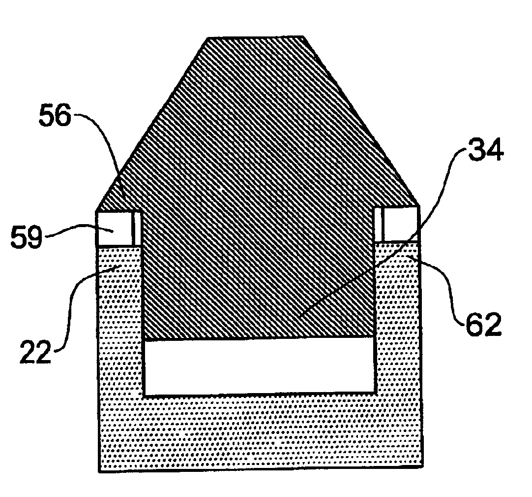
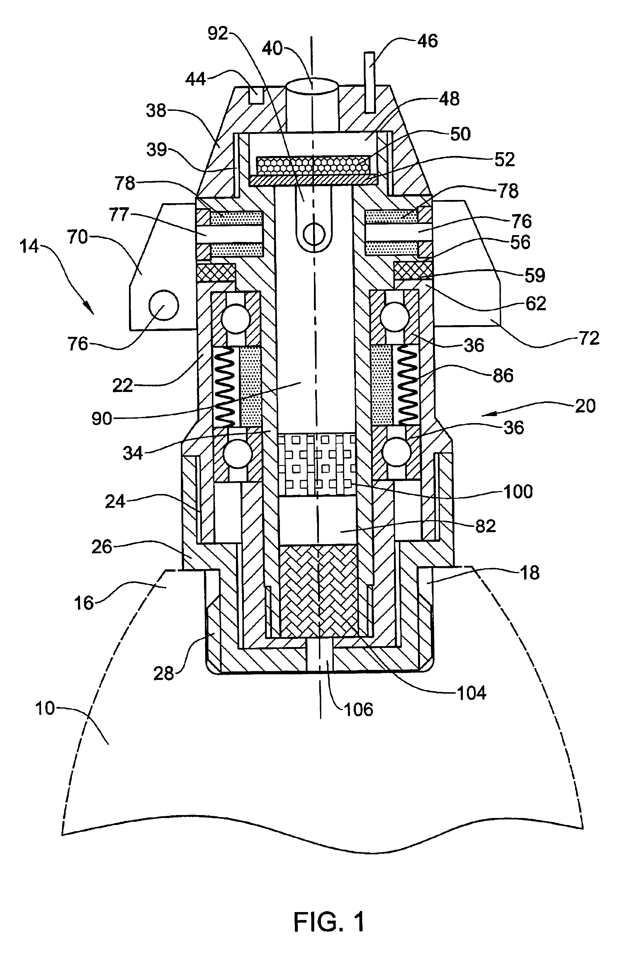
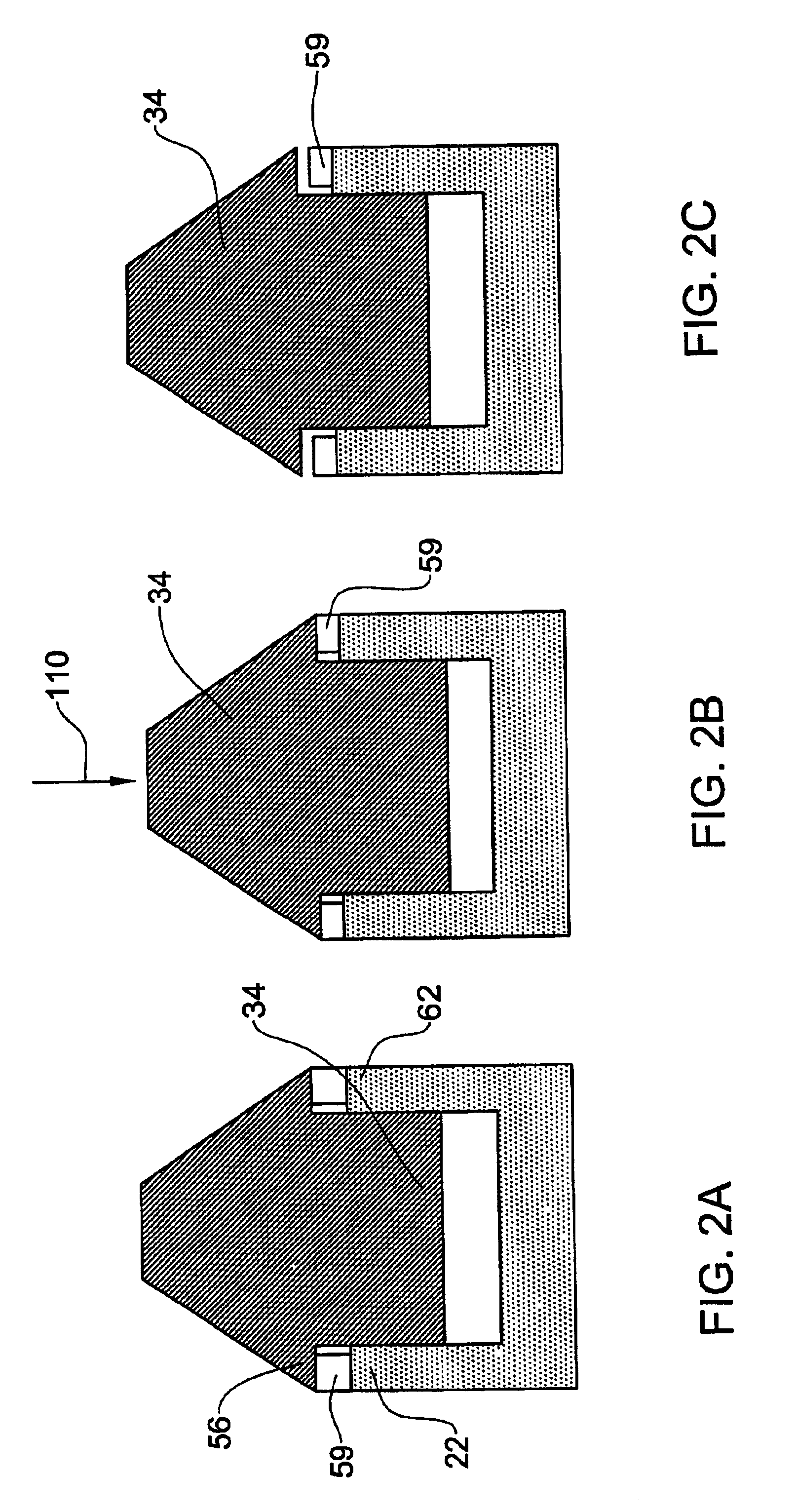
Attention is first directed to FIG. 1 of the drawings wherein a projectile designated 10 (only a front portion thereof is shown, in dashed lines) is fitted with an imaging fuse in accordance with the present invention generally designated 14. For the sake of example only, projectile 10 is a shell adapted for launching from a gun. Projectile 10 is formed at its fore end 16 with a fuse receptacle 18 for readily coupling thereto a fuse by screw engagement, though other coupling arrangements are also possible e.g. bayonet coupling etc. It is to be appreciated that the imaging fuse 14 is merely an option whereas other fuses may be coupled thereto for igniting the main charge of the projectile 10, e.g. a strike fuse, a delay fuse, a heat sensing fuse, etc.

The imaging fuse 14 comprises a housing 20 consisting of a front housing member 22 screw coupled at 24 to a rear housing member 26 formed in turn, at its rear end with a threading 28 for screw engagement within receptacle 18 of the proje...


PUM


Abstract

An imaging fuse comprising a housing fixable within a receptacle at a fore end of a projectile, a coaxial support frame rotatably supported within the housing and fitted with an imaging assembly. The support frame is axially displaceable with respect to the housing. An axial shock absorbing system is provided intermediate the housing and the support frame, and a spin suppressing mechanism is associated with the support frame, for suppressing rotation of the support frame with respect to the housing.

Description

This invention relates to an imaging device. More specifically the invention is concerned with an imaging fuse attachable to an airborne object, such as a projectile. The invention is also concerned with a system and method making use of such an imaging device.The term projectile as used herein the specification and claims is used to denote any type of launched / fired object, either self propelled e.g. a rocket, a missile, etc, or a kinetic projectile e.g. a shell, a projectile fired from a gun or canon, a mortar, a high caliber machine gun, etc.BACKGROUND OF THE INVENTION AND PRIOR ARTAn imaging projectile may be of many configurations and may be launched towards its destination by different means. The projectile may be a self-propelled type in which it is fitted with a rocket or other type of engine and may also comprise remote control or other steering arrangements for guiding the projectile towards its destination. The projectile may alternatively be a kinetic body launched / fired...

Claims


Application Information

Patent Timeline
Patent Type & Authority Patents(United States)
IPC IPC(8): F42C11/00F42B15/00F42B15/08F42B12/36F42B12/02F41G3/00F41G3/02
CPCF41G3/02F42B12/365F42B15/08F42C11/002
Inventor ORON, ELIEZER
Owner GEO T VISION
Why Eureka
Try Eureka