Method of making printed battery structures

a battery structure and printed technology, applied in the field of battery structures, can solve problems such as difficulty in making small batteries of different configurations

Inactive Publication Date: 2004-08-24
HEWLETT PACKARD DEV CO LP
View PDF5 Cites 48 Cited by
  • Summary
  • Abstract
  • Description
  • Claims
  • Application Information

AI Technical Summary

Problems solved by technology

The number of electronic devices that utilize batteries is increasing, for example as a result of more portable devices being marketed, and are also becoming smaller.
It can be difficult to make small batteries of different configurations.

Method used


Image

  • Method of making printed battery structures
  • Method of making printed battery structures
  • Method of making printed battery structures

Examples


Embodiment Construction

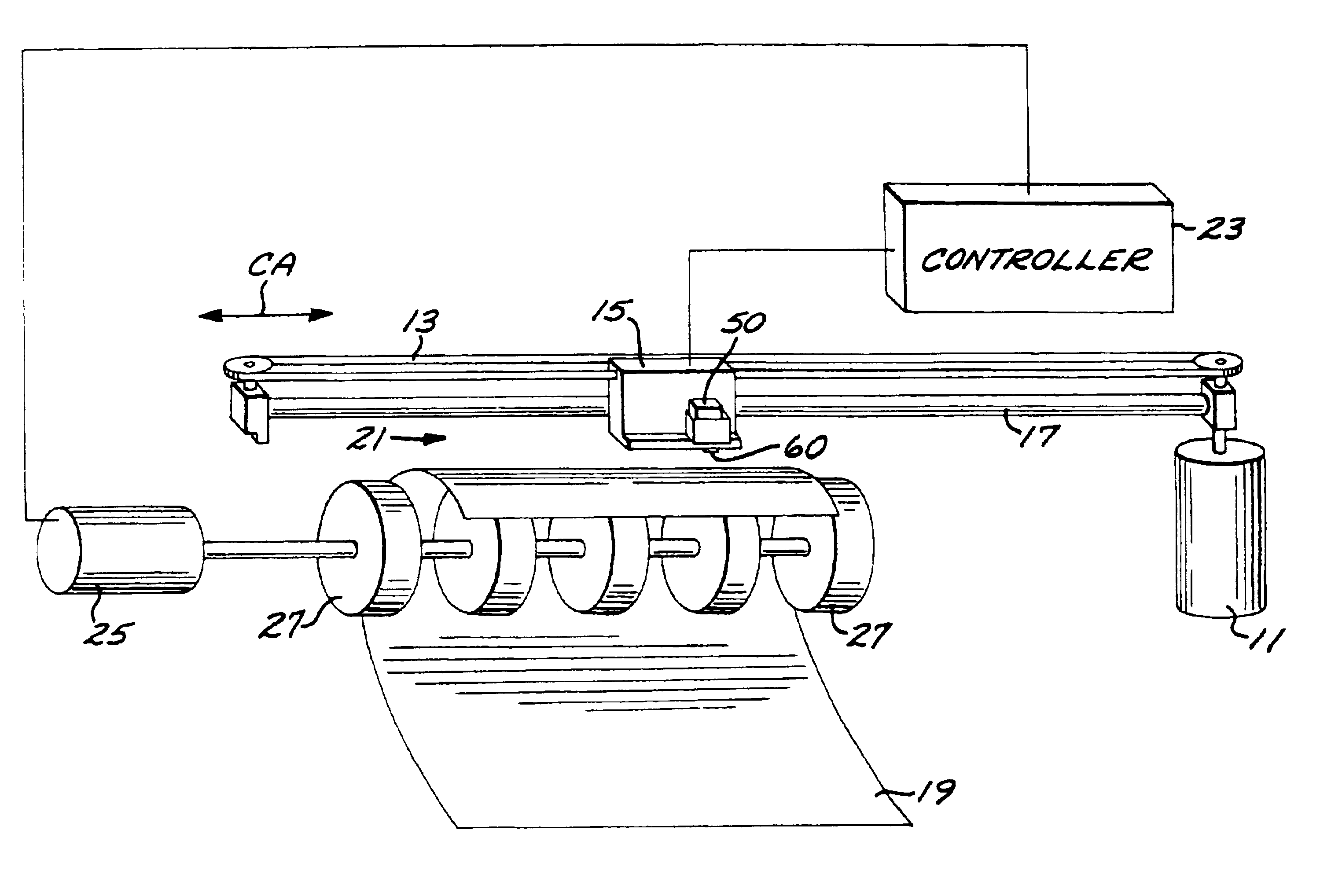
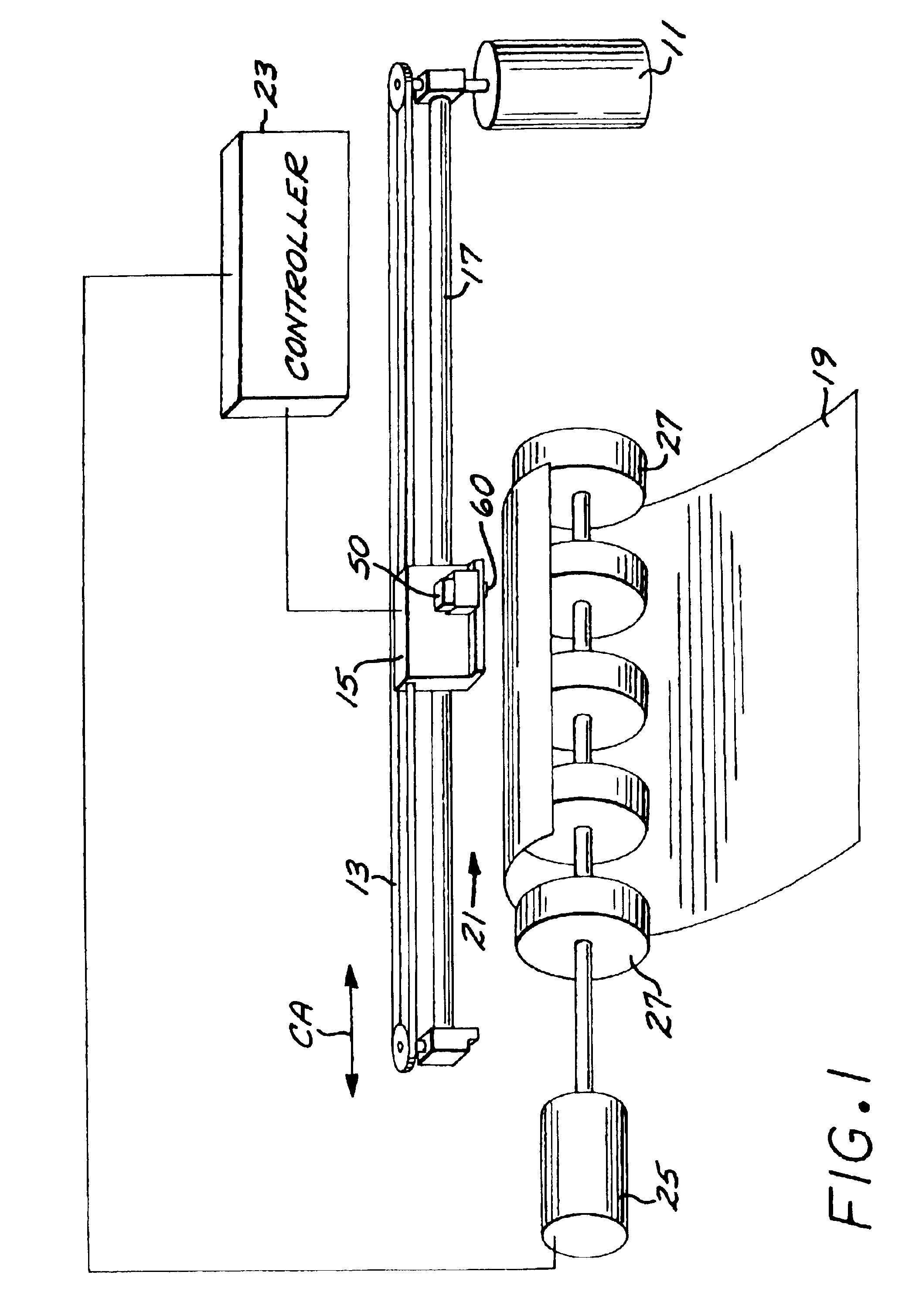
FIG. 1 is a schematic block diagram of an embodiment of a drop on demand printing apparatus that can be employed to print battery structures such as those disclosed herein. The drop on demand printing system includes a carriage drive motor 11 that drives a drive belt 13 back and forth as the drive motor reverses direction. The drive belt 13 is attached to a print carriage system 15 that is slidably mounted on a slider rod 17, and the print carriage system thus scans laterally back and forth along a carriage scan axis CA from left to right and right to left. The print carriage system 15 includes one or more print cartridges 50 that can be mounted side by side, for example. Each of the print cartridges 50 includes a drop on demand drop emitting printhead 60 having a plurality of drop generators for depositing drops on a portion of a carrier medium 19 that is located in a print zone 21 that underlies the area or region swept by the drop generators as the print carriage 15 is scanned. T...


PUM

PropertyMeasurementUnit
areaaaaaaaaaaa
conductiveaaaaaaaaaa
thermalaaaaaaaaaa

Abstract

A battery is made by drop on demand printing a first electrode pattern and a second electrode pattern, and applying an electrolyte region over a portion of the first electrode pattern and a portion of the second electrode pattern.

Description

BACKGROUND OF THE DISCLOSUREThe subject disclosure is generally directed to battery structures, and more particularly to battery structures that are formed by drop on demand printing.The number of electronic devices that utilize batteries is increasing, for example as a result of more portable devices being marketed, and are also becoming smaller. It can be difficult to make small batteries of different configurations.Features and advantages of the disclosure will readily be appreciated by persons skilled in the art from the following detailed description when read in conjunction with the drawing wherein:FIG. 1 is a schematic block diagram of an embodiment of a printing apparatus that can be used to print components of a battery.FIGS. 2A and 2B schematically illustrate an embodiment of electrode patterns of a battery that can be printed by a printing apparatus.FIGS. 3A and 3B schematically illustrate an embodiment of an electrolyte region disposed over printed electrode patterns of ...

Claims


Application Information

Patent Timeline
Patent Type & Authority Patents(United States)
IPC IPC(8): H01M6/00H01M10/26H01M10/24H01M10/04H01M4/04H01M6/40B41J3/407H01M4/38H01M4/50H01M6/12
CPCB41J3/407H01M4/0404H01M4/0414H01M6/12H01M6/40H01M6/005H01M4/38H01M4/50Y10T29/49115H01M2300/0014Y10T29/53135Y02P70/50
Inventor HOPKINS, GLEN A.CHILDERS, WINTHROP D.DOUMAUX, HOWARD A.
Owner HEWLETT PACKARD DEV CO LP
Why Eureka
Try Eureka