Move-away arrow rest

a technology of arrow rest and arrow head, which is applied in the direction of compressed gas guns, white arms/cold weapons, weapons, etc., can solve the problems of difficult fine tuning of rigid linkages, reduced flexible member length, and relatively complex rigid linkages

Inactive Publication Date: 2004-08-31
NEW ARCHERY PRODS
View PDF18 Cites 38 Cited by
  • Summary
  • Abstract
  • Description
  • Claims
  • Application Information

AI Technical Summary

Benefits of technology

When the arrow shaft is positioned within the holding apparatus, such as when the arrow rest is in the unloaded position, the archery bow can be carried or moved into many different positions and the holding apparatus maintains the arrow shaft in a generally fixed position with respect to the archery bow. The holding apparatus of this invention prevents the arrow shaft from falling off of a shelf of the riser portion.
In one embodiment of this invention, the holding apparatus is wider than a diameter of the arrow shaft and thus the arrow shaft can move, to a limited extent, within the holding apparatus. The limited movement is acceptable because when the arrow rest moves into a loaded position, the arrow rest contacts and self-centers the arrow shaft with respect to the arrow rest and precisely positions the arrow shaft in a shooting window. In one embodiment of this invention, the arrow rest has two prongs that are spaced apart from each other. The prongs can easily center the arrow shaft on the arrow rest by simply using gravity forces.
In one embodiment of this invention, inside surfaces of walls forming the holding apparatus have a matte finish that provides enough friction between the inside surface and the arrow shaft to hold the arrow shaft within the holding apparatus, even when the archery bow is rotated, tilted or otherwise moved. Such feature allows an archer to mount an arrow by attaching a nock end to the bow string, and place the arrow shaft within the holding apparatus. When the bow string is not drawn back far enough to lift a pivotal arrow rest, in one embodiment, the walls frictionally hold the arrow shaft. Thus, an archer can load an arrow with respect to a bow and place the arrow shaft within the holding apparatus, and then carry the bow through different field conditions, without the arrow shaft falling or otherwise moving away from an area of the bow riser. When an archer spots a target, the archer can then place the archery bow into a firing position. With the pivotal arrow rest according to this invention, the archer can then draw the bow string and thereby pivot the arrow rest into a loaded position, which lifts the arrow shaft out of and away from the holding apparatus. When the arrow is discharged from the archery bow, neither the arrow shaft nor the fletching contact or interfere with the arrow rest or with the holding apparatus.
When an arrow rest can instantaneously or immediately pivot or otherwise move away from the arrow shaft and the fletching during, launch or discharge of an arrow, there is a much greater chance that the arrow rest will not interfere with a flight path of the arrow. The arrow rest according to this invention uses a flexible inelastic member as a linkage between the bow cable and the arrow rest. Because the flexible member of this invention is also inelastic, there is no relatively short time period necessary, such as associated with the previously discussed conventional arrow rests, for the flexible inelastic member of this invention to decrease in length. The flexible inelastic member of this invention instantaneously or immediately overcomes the return bias force and thus the arrow rest of this invention instantaneously or immediately begins acting to move the arrow rest away from the discharged arrow.
In one embodiment of this invention, the flexible inelastic, member is a cable that preferably but not necessarily has an outer coating or a sheath. In another embodiment of this invention, the flexible inelastic member is a plastic rod. The flexible inelastic member according to this invention preferably has a relatively low modulus of elasticity, which provides a relatively low resistance to bending.

Problems solved by technology

One problem with some conventional flexible members is that when the bow string is released, the length of the flexible member decreases for a certain relatively short time period, until the return bias force of the arrow rest can again overcome the tension force in the flexible elastic member and thus return the arrow rest to the unloaded position.
However, even with the relatively short time period the arrow shaft is discharged before the conventional flexible elastic member allows the arrow rest to move sufficiently away from the loaded position.
However, rigid linkages are difficult to finely tune or are relatively intricate.

Method used


Image

  • Move-away arrow rest
  • Move-away arrow rest
  • Move-away arrow rest

Examples


Embodiment Construction

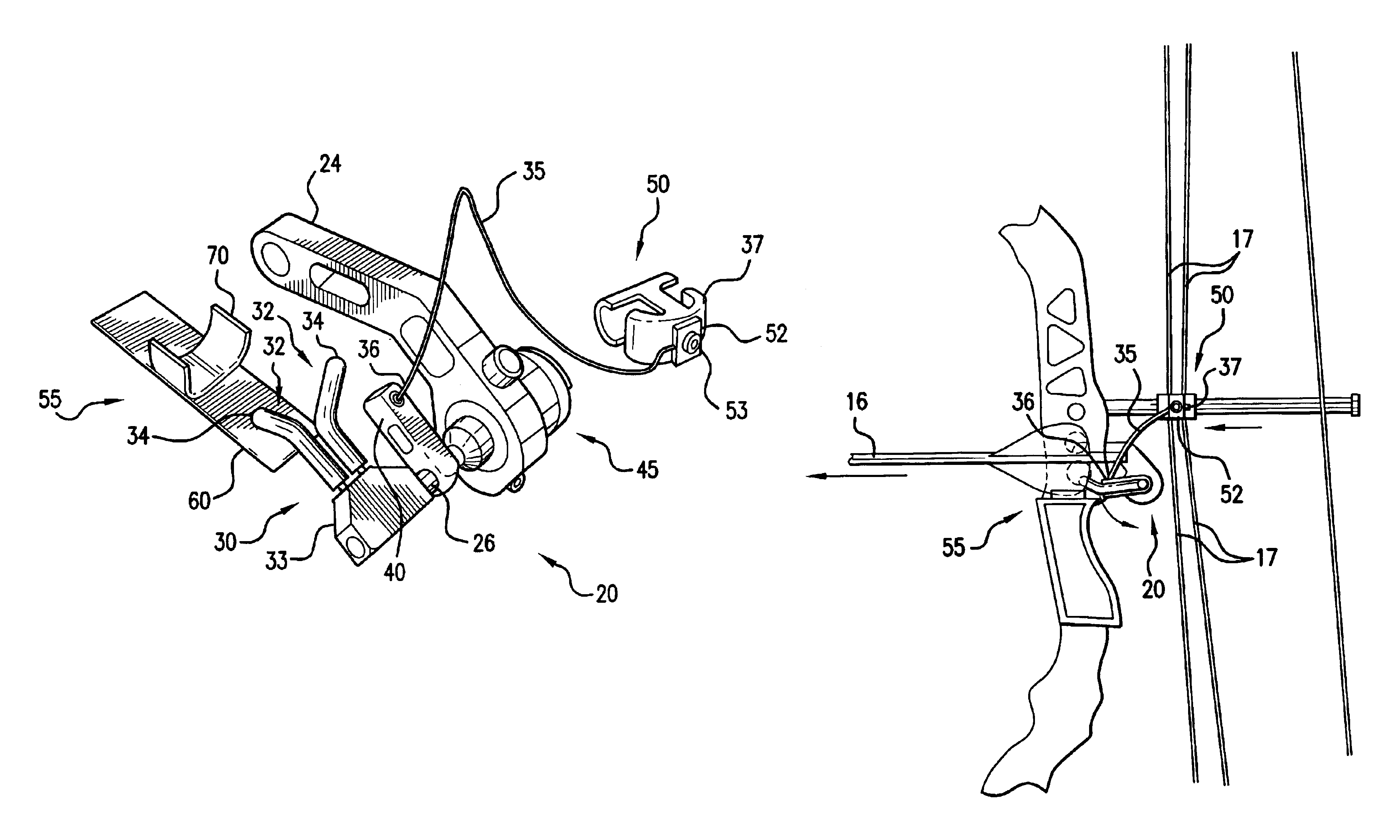
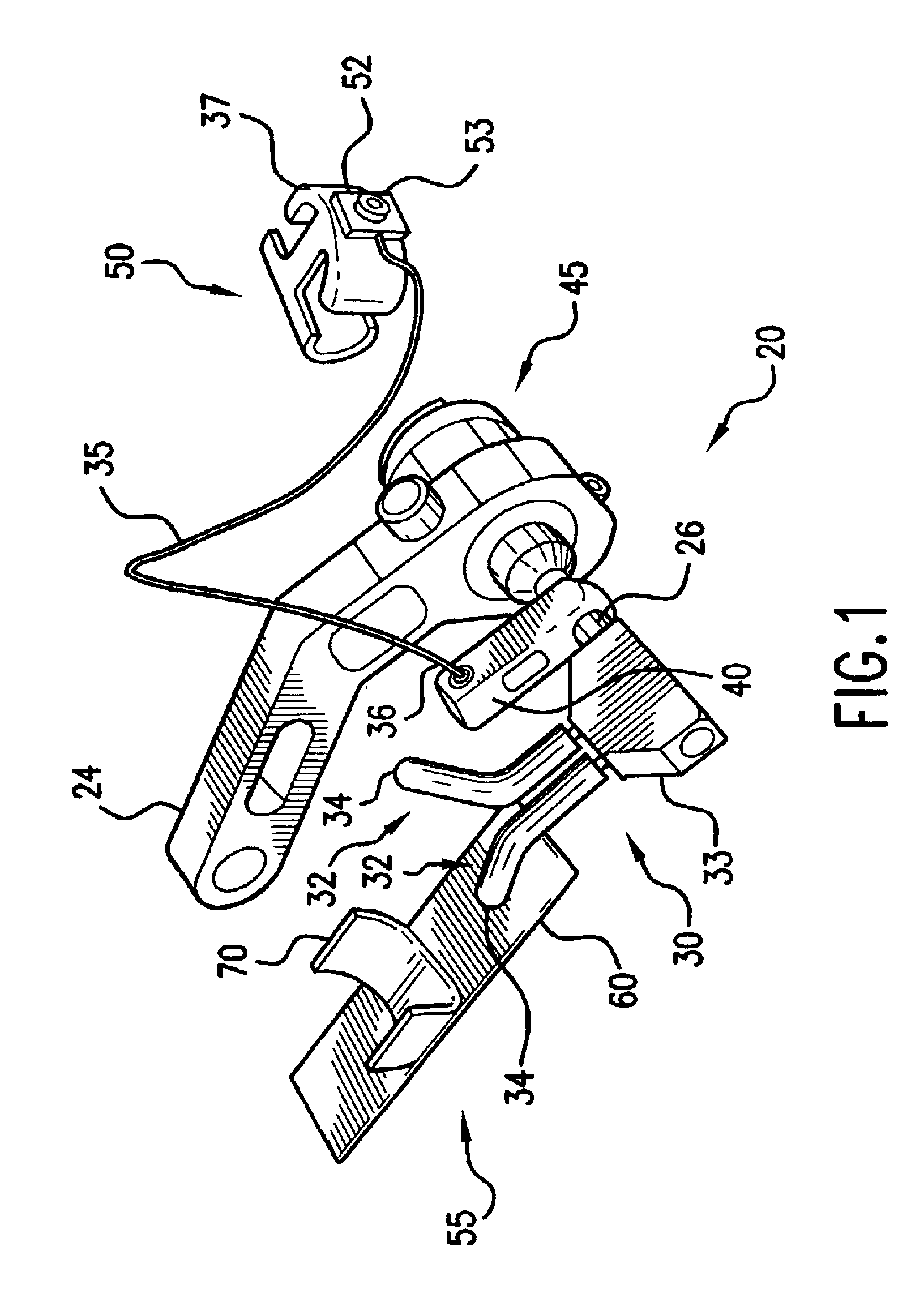
FIG. 1 shows a perspective view of arrow rest 20 and holding apparatus 55, according to one embodiment of this invention. As shown in FIG. 1, arrow rest 20 and holding apparatus 55 are separate individual components. Bracket 24 or any other similar structure can be used to attach arrow rest 20 with respect to archery bow 15. Holding apparatus 55 can be secured with respect to archery bow 15 using double-sided tape or another suitable adhesive or adhesive layer.

When arrow rest 20 is mounted with respect to archery bow 15, at least one arm 32, two arms 32 as shown in FIG. 1, each is pivotally mounted with respect to archery bow 15. Cable slide 50 is attached with respect to at least one bow cable 17 of archery bow 15.

As shown in FIG. 1 support element 30 pivots or is otherwise moveable between a first position and a second position, such as an unloaded position and a loaded position, of support element 30 with respect to archery bow 15. FIGS. 10 and 11 show diagrammatic views of arrow...


PUM


Abstract

A pivotally mounted arrow rest that has a support element moveable between a loaded position and an unloaded position. A bias element urges the support element toward the unloaded position. A flexible inelastic member has a first end portion fixed with respect to a bow cable and a second end portion operatively connected to support element. When the support element is in the loaded position, the flexible inelastic member is in a tension condition.

Description

1. Field of the InventionThis invention relates to a move-away or drop-away arrow rest that pivots between a first position and a second position with respect to an archery bow and that also moves away from an arrow shaft and fletching when an arrow is launched or discharged from the archery bow. This invention also relates to an apparatus for holding an arrow with respect to the archery bow, particularly when the arrow is loaded on a bow string of the archery bow, in an unloaded or at rest condition.2. Discussion of Related ArtSome conventional arrow rests move away, drop away, fall away or are otherwise forced away from an arrow shaft as an arrow is launched or discharged from the archery bow. It is known to use a return bias force to move the arrow rest away from the arrow when the arrow is discharged. In conventional arrow rests having the move-away or drop-away feature, flexible elastic members, such as rubber tubing, string, cords or the like have been used to overcome the ret...

Claims


Application Information

Patent Timeline
Patent Type & Authority Patents(United States)
IPC IPC(8): F41B5/22F41B5/00
CPCF41B5/143
Inventor MIZEK, ROBERT S.SIMO, MIROSLAV A.HARWATH, FRANK A.
Owner NEW ARCHERY PRODS
Why Eureka
Try Eureka